• 110kV and 50kV AC SF6 Gas Insulated Voltage Transformer
  • 110kV and 50kV AC SF6 Gas Insulated Voltage Transformer
  • 110kV and 50kV AC SF6 Gas Insulated Voltage Transformer
110kV and 50kV AC SF6 Gas Insulated Voltage Transformer
$1000.00
Model
JDQXF-110-0.5P
Basic info
Brand Wone
Model NO. JDQXF-110 SF6 Gas Insulated Voltage Transformer
Primary voltage 110√3KV
Nominal voltage 110KV
insulation level 126/200/480KV
Series JDQXF-110
Product Detail

Description:

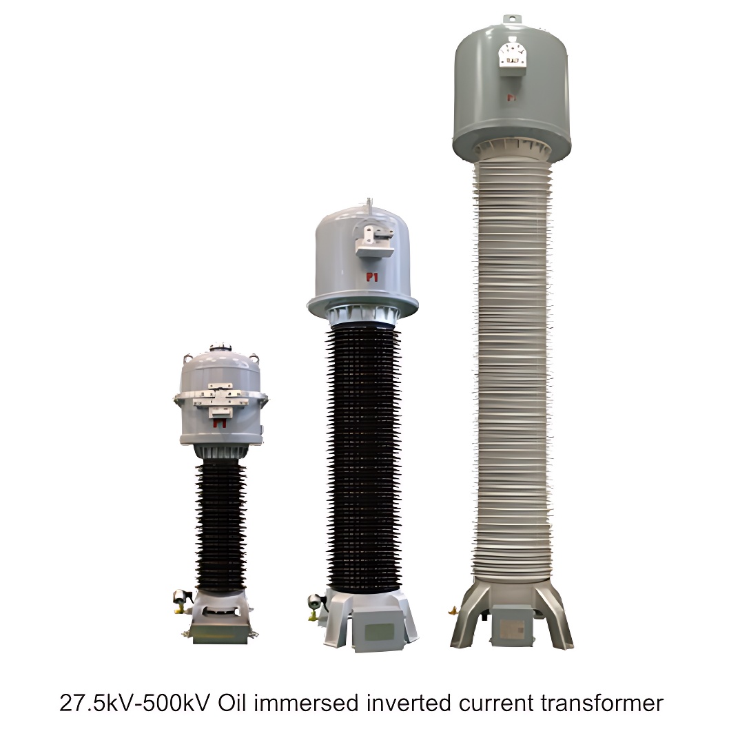
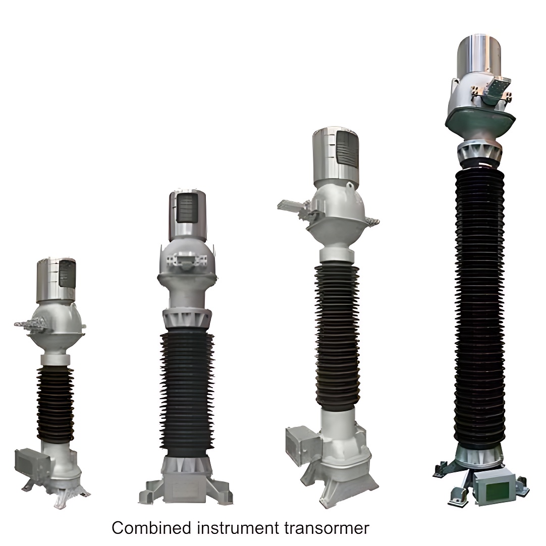
An instrument used to convert voltage. However, the purpose of the transformer to convert the voltage is to facilitate the transmission of electric energy, so the capacity is very large, and it is generally calculated in kilovolt-ampere or megavolt-ampere; The purpose of the voltage transformer is to convert the voltage, which is mainly used to supply power to the measuring instrument and relay protection device, and is used to measure the voltage, power and electric energy of the line.

Industry applications:

It is suitable for outdoor and neutral point effective grounding in 110kV and 50kV AC power systems, for electric energy, voltage measurement and relay protection.

Features:

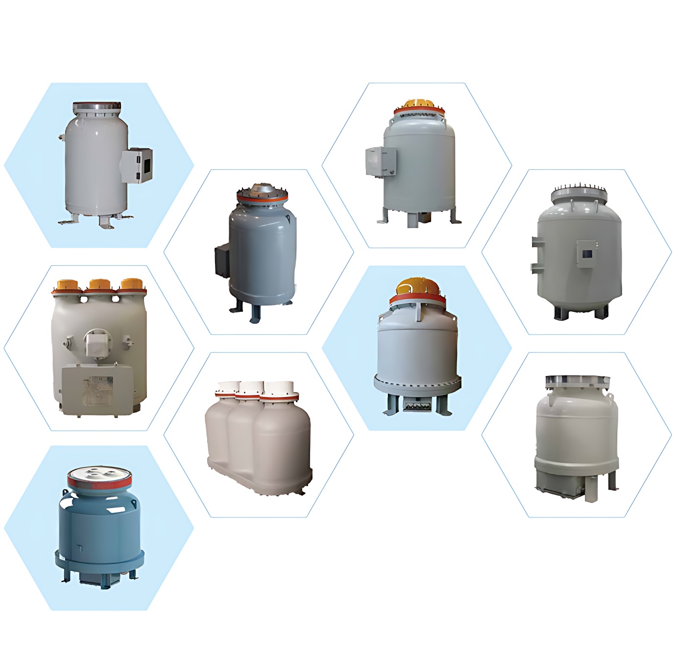
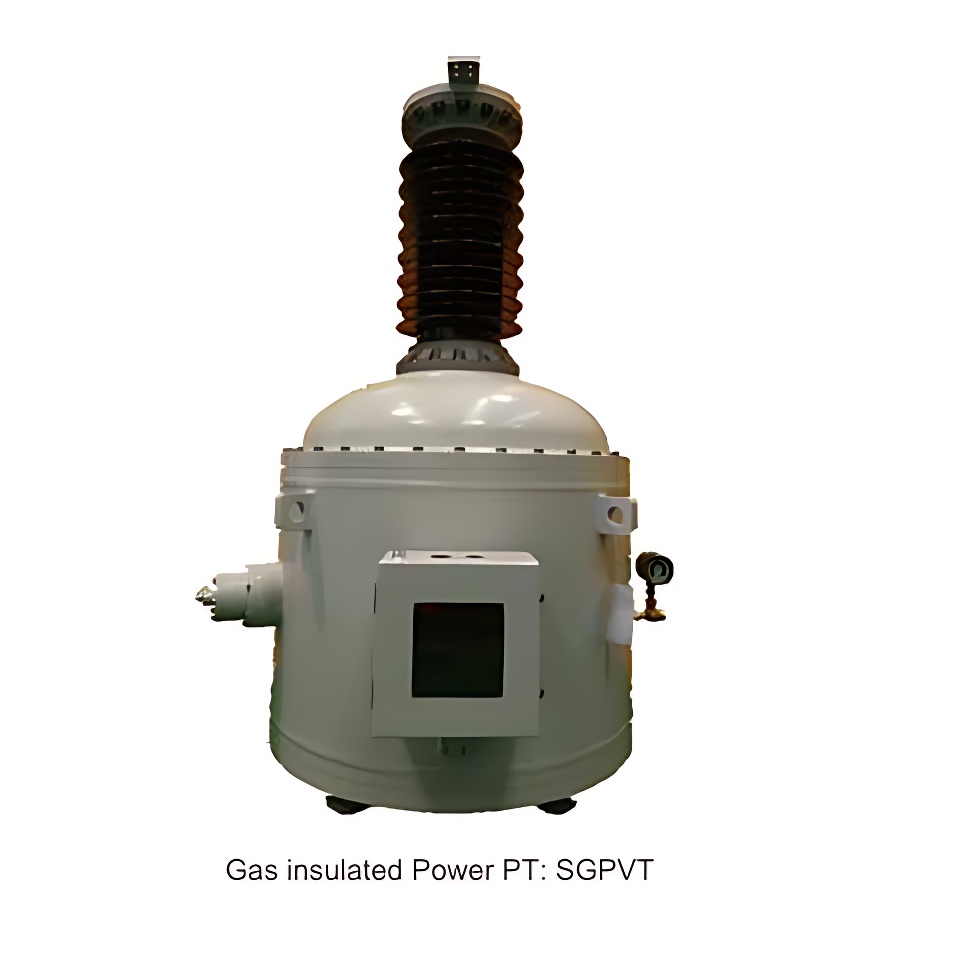
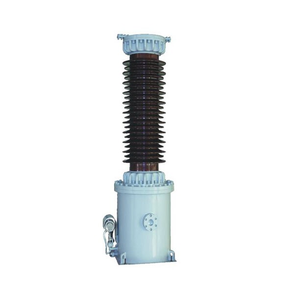
  •  This product is a single-phase, independent SF6 gas-insulated voltage transformer, which adopts a vertical structure, which is composed of several parts, such as a body, a metal shell, a lead pipe and a porcelain sleeve.

  • The transformer windings are single-stage structured, and the composite insulation composed of SF6 gas and rhombic dispensing polyester film can withstand high voltages. The low-voltage winding and high-voltage winding are equipped with internal and external electrostatic screens, and the high-voltage winding is also equipped with a shielding cover to further improve the field strength distribution. The high and low voltage windings are installed on the mouth core in a rectangular shape, and the whole body is fixed in the shell, and the shell is connected to the casing.

  •  The product is equipped with a primary connection plate, a grounding seat, a secondary junction box, an inflatable joint, a pressure gauge (density controller), an adsorbent and an anti-riot sheet.

  •  All sealing parts are sealed with O-shaped sealant gasket and coated with waterproof glue on the outside; The whole product is in a fully sealed state, and the product is filled with gas with rated pressure to ensure the normal operation of the product.

Technical parameters:

image.png


Dimension:

image.png


Product show:

091029818218004659.jpg


Why choose us:

  • We have a professional service team.

  • We have good after-sales.

  • We can guarantee the quality of our products.


Know your supplier
Wone
Main Categories
High voltage/Low voltage/Wire cable/Instrument meters/New energy/Tester/Production equipment/Generator/Electrical fittings/Integrated Electrical Equipment
Business Type
Design/Manufacture/Sales
Highest Annual Export (USD)
$50,000,000
Professional Experience
1 years
Workplace
65666m²m²
占位
占位
Related Products
Related Knowledges
Failure Analysis and Design Optimization of Conventional Grounding Transformers
I. Core Cause of Damage: Electrodynamic Impact (Complying with GB/T 1094.5 / IEC 60076-5)The direct cause of high-voltage winding end collapse is the instantaneous electrodynamic impact induced by short-circuit current. When a single-phase grounding fault occurs in the system (such as lightning overvoltage, insulation breakdown, etc.), the grounding transformer, as the fault current path, withstands high-amplitude and steep-rise-rate short-circuit currents. According to Ampère's force law
Felix Spark
06/12/2025
Analysis of Grounding Transformer Operational Behavior Under System Single-Phase-to-Ground Fault Conditions
1 Theoretical AnalysisIn distribution networks, grounding transformers serve two key roles: powering low - voltage loads and connecting arc - suppression coils at neutrals for grounding protection. Grounding faults, the most common distribution network fault, heavily impact transformers’ operating characteristics, causing sharp changes in electromagnetic parameters and status.To study transformers’ dynamic behaviors under single - phase grounding faults, build this model: Assume a tr
Felix Spark
06/12/2025
Design Calculations for Neutral Grounding Schemes and Grounding Transformer Sizing in Utility-Scale Solar PV Plants
1 Classification of Neutral Grounding Methods for Solar Photovoltaic Power StationsInfluenced by differences in voltage levels and grid structures across regions, the neutral grounding methods of power systems are mainly categorized into non-effective grounding and effective grounding. Non-effective grounding includes neutral grounding via arc suppression coils and neutral ungrounded systems, while effective grounding comprises neutral solid grounding and neutral grounding via resistors. The sel
Dyson
06/12/2025
Zero-Sequence Impedance Characterization of Dry-Type Grounding Transformer with ZN Connection
In a neutral-insulated three-phase power system, an earthing transformer provides an artificial neutral point, which can be solidly earthed or earthed via reactors/arc suppression coils. The ZNyn11 connection is typical, where zero-sequence magnetomotive forces in the inner/outer half-windings of the same core column cancel out, balancing fault currents in series windings and minimizing zero-sequence leakage flux/impedance.Zero-sequence impedance is critical: it determines fault current magnitud
Dyson
06/12/2025
Case Analysis on Maloperation of Grounding Transformer Overcurrent Protection Relay
The neutral grounding mode refers to the connection between the power system neutral point and ground. In China's 35 kV and below systems, common methods include ungrounded neutral, arc-suppression coil grounding, and small-resistance grounding. The ungrounded mode is widely used as it allows short-term operation during single-phase grounding faults, while small-resistance grounding has become mainstream for its fast fault removal and overvoltage limitation. Many substations install grounding tr
Felix Spark
06/12/2025
Discussion on the Design of Low Zero-Sequence Impedance Grounding Transformers
With the expansion of power system scale and the cableization process of urban power grids, the capacitive current in 6kV/10kV/35kV power grids has significantly increased (generally exceeding 10A). As power grids at this voltage level mostly adopt neutral ungrounded operation mode, and the distribution voltage side of main transformers is usually in delta connection, lacking a natural grounding point, the arc during ground faults cannot be reliably extinguished, necessitating the introduction o
Dyson
06/11/2025
×
Inquiry
Download
Experts Electrical is dedicated to serving the personnel in the global power industry.
Join Experts Electrical, not only can you discover power equipment and power knowledge, but also canhnd like - minded friends!
商品视频播放