| Brand | Vziman |
| Model NO. | 100KVA 15KV 3 PhaseOil-immersed distribution transformer |
| Rated voltage | |
| Rated capacity | 100kVA |
| Primary voltage | 15kV |
| Secondary voltage | 0.4kV |
| No-load loss | >320W |
| Load loss | >170W |
| Series | S-M |
Description:
Oil immersed transformer, use ourcompany special calculation and validation procedures to make sure theperformance of products. superior process equipment, elaborate materialselecting and efficient manufacturing make the transformer have smallvolume,light weight,low loss,low partial discharge,low noise characteristics.
The product is stable,reliable,economic, environmental protection. lt can beapplied to many places such as power plants,transformer substation ,largeindustrial mining and petrochemical enterprise and so on.
Features:
Ultralow no-load loss.
Energy saving and great power consuming efficiency.
Copper/ aluminum coil winding, strong short circuit resistance ability.
Dyn11 coil connection decrease the influences of harmonic wave.
Fully sealed structure for maintenance free.
Slow insulation aging & longer serving life.
Parameters:
Oil-immersed distribution transformer three-phase |
|
Model NO. |
S-M-100/15/0.4 |
Product classification |
Distribution transformer |
Rated capacity |
100kVA |
Primary voltage |
15kV |
Secondary voltage |
0.4kV |
Number of phase |
3 |
Number of winding |
2 |
Rated frequency |
50Hz |
Tap changer |
OCTC |
Tap range |
±2×2.5% |
Vector group |
Dyn11 |
Cooling system |
ONAN |
No-load loss |
>320W |
Load loss |
>170W |
Impedance |
4% |
Basic insulation level |
—— |
Winding material ( H.V & L.V) |
Copper |
The way the bushing appears |
Porcelain |
Power frequency withstand voltage |
38kV |
Lightning impulse |
—— |
The temperature rise—Winding |
62k |
The temperature rise --Top oil |
57k |
Tank color |
—— |
Creepage distance |
>576mm |
Fitting requirement |
—— |
Environmental requirement |
—— |
Transformer structure |
Sealed |
Standard |
IEC60076 |
Port of loading |
—— |
HS code |
—— |
Transportation |
—— |
External dimensions:
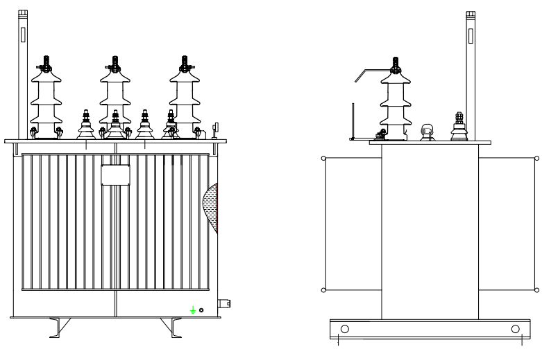
Size |
885mm×875mm×1120mm |
Weight |
590KG |
Environmental requirement:
Max. ambient temperature |
—— |
Altitude |
—— |
Product show:

How to choose the model and specification of oil-immersed three-phase distribution transformer according to load capacity?
First, it is necessary to determine the total power of the loads to be supplied. For residential areas, this involves considering the total power of all household electrical appliances, including lighting fixtures, televisions, refrigerators, air conditioners, etc. For example, in a residential area with 100 households, if the average power consumption per household is 5 kW (considering the simultaneous use factor), the total load power would be approximately 500 kW.
In industrial settings, it is necessary to tally the power of all production equipment, lighting, and office devices within the factory. For instance, in a small mechanical processing plant, the total power of machine tools might be 300 kW, and adding the power of lighting and office devices, the total load power could reach around 350 kW.
The simultaneous factor refers to the probability that all loads will operate simultaneously at any given moment. In residential areas, the simultaneous factor is generally between 0.4 and 0.6. In industrial settings, it is determined based on production shifts and equipment operating patterns, typically ranging from 0.7 to 0.9.
The power factor reflects the efficiency of energy utilization by the load. In scenarios with a high proportion of inductive loads (such as motors), the power factor is lower, usually between 0.7 and 0.9. It is essential to calculate based on actual load conditions and then select the transformer capacity based on the calculated actual load capacity.
