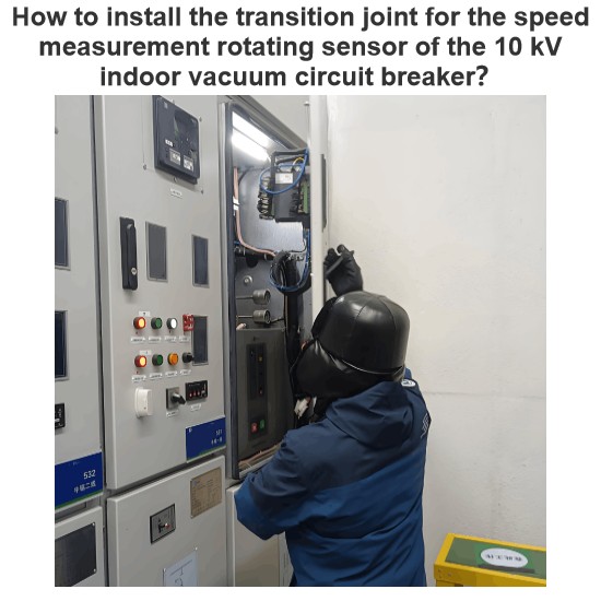
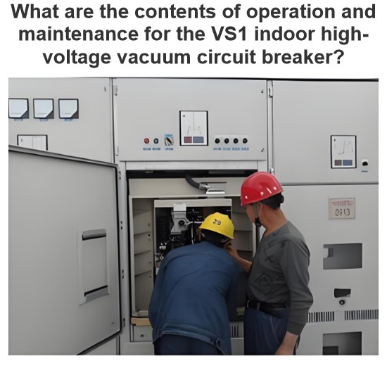
Installation and Debugging of Vacuum Circuit Breaker

Installation Requirements
- All parts and components must pass inspection before installation.
- Work - position tools and equipment used for installation must be clean and meet assembly requirements. When tightening fasteners, use fixed wrenches, box wrenches, or socket wrenches. Do not use adjustable wrenches when tightening screws near the arc - extinguishing chamber.
- The installation sequence should comply with the installation process regulations, and the specifications of fasteners for each component installation must be in accordance with the design requirements. In particular, the length specification of the bolts fixing the static contact end of the arc - extinguishing chamber must be correct .
- After assembly, the pole - to - pole distance and the position distances of the upper and lower outgoing lines should meet the requirements of the drawing dimensions.
- After assembly, all rotating and sliding parts should move freely. Lubricating grease should be applied to the areas subject to motion - induced friction.
- After passing the adjustment test, clean and wipe the equipment. Mark the adjustable connection parts of all components with red paint dots. Apply Vaseline to the outgoing terminals and protect them with clean paper wrapping.
Installation
Taking the ZN39 vacuum circuit breaker as an example, its assembly generally involves three parts: the front part, the upper part, and the rear part.
Front - part Installation Sequence:
- First, position the framework.
- Then install the post insulators, followed by the horizontal insulators.
- Next, attach the bracket, the lower busbar, the arc - extinguishing chamber and the parallel insulating rods.
- After that, install the upper busbar, the flexible connection of the conductive clamp, the contact spring seat sliding sleeve, and finally the triangular toggle arm.
Upper - part Installation Sequence:
- Install the main shaft and the bearing seat first.
- Then mount the oil buffer.
- Finally, attach the insulating push rod.
Rear - part Installation Sequence:
- Install the operating mechanism first.
- Then attach the opening spring, the counter, the closing and opening indicators, and the grounding mark.
Connect these three major parts as follows:
- Connect the front part and the upper part: Use a pin to connect the adjustable universal joint of the insulating push rod to the triangular toggle arm.
Adjustment of Mechanical Characteristics
Preliminary Adjustment
Preliminary adjustment mainly focuses on roughly adjusting the contact opening distance and contact travel for each pole of the assembled vacuum circuit breaker. During the preliminary adjustment, manually close the circuit breaker slowly and check whether all parts are installed and connected correctly. When adjusting, it is crucial not to set the contact travel too large to avoid the contact closing spring from being compressed too much. Therefore, during installation, it is advisable to shorten (screw in) the adjustable joint of the insulating push rod. Once the manual operation is normal, the measurement and adjustment of the opening distance and contact travel can be carried out, which will be introduced separately below.
Adjustment of Opening Distance and Contact Travel
For various types of vacuum circuit breakers, based on the relative positions of the moving contact rod's movement axis and the contact closing spring axis, they can generally be divided into two types:
- Coaxial type: The axis of the moving contact cup coincides with the axis of the closing spring.
- Hetero - axial type: The axis of the moving contact rod is separated from the axis of the closing spring. The closing spring is installed on the axis of the insulating push rod, and the positions of the two axes are nearly perpendicular. (Please refer to our company's ZN28A type split - type vacuum circuit breaker, as shown in Figures 1 and 2.)
The calculation methods for the opening distance and contact travel of these two types of circuit breakers are slightly different.
The mechanical characteristic tables of various vacuum circuit breakers provide data on the nominal opening distance and contact travel. After manually closing and opening the circuit breaker to measure the opening distance and contact travel, the following adjustment methods can be used to ensure they meet the technical specifications.
Adjustment of Coaxial Structure
If the total stroke (which is equal to the sum of the opening distance and the contact travel) is less than the sum of their nominal values, it means that the rotational movement of the switch main shaft is insufficient. In this case, the adjustable connecting rod that connects the operating mechanism to the main - shaft toggle arm should be adjusted to be longer; conversely, if the total stroke is greater, it should be adjusted shorter to make the total stroke basically meet the requirements. This is the first step.
In the second step, adjust the distribution between the opening distance and the contact travel within the total stroke. At this time, only the length of the threaded connection at the front end of the insulating push rod for each pole needs to be adjusted. When lengthening the connection, the opening distance fo increases while the compression stroke Jc decreases; when shortening it, the opening distance fo decreases and the contact travel Jc increases. The minimum adjustment range of the threaded joint is half a turn (either screwing in, which is equivalent to shortening the length of the insulating push rod, or screwing out, which is equivalent to increasing its length), that is, half of the pitch.
The threaded joint of the insulating push rod is also used to adjust the three - pole synchronism. Therefore, during the adjustment process, it is necessary to ensure that both the opening distance and the contact travel are within the tolerance range, while also taking into account the three - pole synchronism. Usually, it takes multiple manual closing and opening operations to complete the adjustment. Throughout the adjustment process, special attention should be paid not to exceed the maximum allowable range of the contact travel, so as to prevent the contact closing spring from being over - compressed and causing damage to the components.
Adjustment of Hetero - axial Structure
In this type of circuit breaker, since the contact spring axis and the moving contact axis are not on the same straight line, the above - mentioned total stroke calculation has no physical meaning here, and the adjustment method is different.
- Opening distance: This type of circuit breaker is equipped with a component called the "opening distance adjusting pad". Its base plate is fixed on the framework. The number of shims can be increased or decreased to change its height. The top is pressed by a toggle arm welded from the main shaft. By changing the height of the adjusting pad, the initial angle of the main shaft in the open - circuit state can be changed. After being transmitted through the insulating push rod, the contact opening distance is thus changed.
- Contact travel: The pre - compression height B1 of the contact spring is determined by the diameter of the compression roller and cannot be changed. After closing, the final compression height B2 of the contact spring can be adjusted in the following two ways:
- Method A: Rotate the threaded connection joint at the end of the insulating push rod in or out. When screwing in (that is, when the distance between the pin holes at both ends of the insulating push rod is shortened), B2 increases and the contact travel decreases; when screwing out, the opposite occurs and the contact travel increases.
- Method B: Adjust the length of the adjustable connecting rod between the operating mechanism and the driving toggle arm of the circuit breaker main shaft, which can also change B2. When the connecting rod is extended, B2 decreases and the contact travel increases; conversely, when it is shortened, the contact travel decreases.
During the adjustment process of the opening distance and contact travel, it is also necessary to adjust the three - pole non - synchronism simultaneously. Make mutual compromises and repeatedly adjust to ensure that all are within the allowable tolerance range.
Adjustment of Auxiliary Switch Interlock
After manually adjusting the opening distance and contact travel, the interlock position of the auxiliary switch must be adjusted before performing electric closing and opening operations. Otherwise, electrical components may be burned out.
During adjustment, disconnect the interlock at one end of the connecting rod between the auxiliary switch and the main - shaft toggle arm. Manually close the circuit breaker, and simultaneously turn the auxiliary switch to the just - tripped position. Adjust the length of the adjusting bolt and the connecting rod so that the pin holes of the connecting rod and the adjusting bolt are approximately aligned. Then, manually open the circuit breaker and turn the auxiliary switch to the just - tripped position again. Also ensure that the pin holes of the connecting rod and the adjusting bolt are approximately aligned. Repeat the adjustment multiple times until the above requirements are met, and then insert the pin. The goal is to ensure that the electrical contacts of the auxiliary switch can be cut off slightly in advance at the end of the closing or opening stroke of the circuit breaker.
Mechanical Characteristic Parameter Testing, Adjustment, and Factory - acceptance Tests
Characteristic Testing
After the preliminary adjustment of the opening distance, contact travel, and auxiliary switch, electric closing and opening operations can be carried out, and mechanical characteristic parameters such as closing and opening time, speed, non - synchronism, and closing bounce can be measured.
There are mainly two types of testing instruments for mechanical characteristic parameters: the optical oscilloscope and the switch characteristic measuring instrument. The former is more accurate and intuitive; the latter is simple and quick to operate, and its accuracy can meet the operational requirements, making it suitable for on - site use. The specific testing methods are not described here.
Fine - tuning of Mechanical Characteristics
After testing, fine - tune the non - compliant parameters to optimize all mechanical characteristic parameters as much as possible.
- Fine - tuning of Non - synchronism:Identify the phase with the greatest difference in closing and opening times through measurement. If this pole closes too early (late), slightly increase (decrease) its opening distance. Since the opening distances of the three poles have been adjusted to be approximately the same, at this time, the adjustment can be achieved by screwing in (out) the adjustable joint of the insulating pull rod of this pole by half a turn. Generally, the non - synchronism of closing and opening can be adjusted to within 1ms.
- Fine - tuning of Closing and Opening Speeds:The closing and opening speeds are affected by various factors. However, the main adjustable components are generally the opening spring and the contact travel. The tightness of the opening spring affects the opening speed, while the contact travel (the compression amount of the contact pressure spring) has a major influence on the opening speed.
For example, when the closing speed is too high and the opening speed is too low, the contact travel can be increased or the opening spring can be tightened; conversely, it can be loosened. Another example is when the closing speed is appropriate but the opening speed is low. In this case, the total stroke can be adjusted to increase it by approximately 0.1 - 0.2mm. At this time, the contact travel of each pole will increase by 0.1 - 0.2mm, and the opening speed will also increase. Conversely, if the opening speed is too high, the contact travel can be adjusted to decrease by 0.1 - 0.2mm, and the speed will decrease accordingly.
After adjusting the non - synchronism and speed, the opening distance and contact travel data of each pole should be re - measured and corrected. The data should be within the specified range of the product.
Elimination of Closing Bounce
There are four possible causes for the closing bounce of a vacuum circuit breaker:
- First, the closing impact rigidity is too high, causing the moving contact to axially rebound.
- Second, the guiding of the moving contact rod is poor, resulting in excessive shaking.
- Third, the gap in the transmission link is too large, especially the transmission gap between the initial compression end of the contact spring and the conductive rod.
- Fourth, the perpendicularity between the contact surface and the central axis is insufficient, causing lateral slippage during contact, which is reflected as "bounce" in the oscillogram or testing instrument.
To reduce or eliminate closing bounce, in the structural design, it is necessary to ensure that the overall structural impact rigidity is not too high (but this cannot be changed for a finished product), and the gap in the guiding structure of the moving contact rod should not be too large.
In a coaxial structure, since the contact pressure spring is directly connected to the conductive rod without intermediate transmission parts, there is no gap. However, in a hetero - axial structure, there is a triangular toggle arm for direction change between the contact spring and the moving contact rod, which is connected by three pins. This creates three gaps, making bounce more likely to occur compared to the former.If bounce (slippage) occurs due to insufficient perpendicularity of the contact end face of the arc - extinguishing chamber, the arc - extinguishing chamber can be rotated by 90°, 180°, and 270° for trial assembly to find the position where the upper and lower contact surfaces fit well.
Usually, this can solve the problem. If it doesn't work, the arc - extinguishing chamber needs to be replaced. During the process of dealing with closing bounce, all screws should be tightened to avoid the interference of vibration.
Factory - acceptance Test
After all the above - mentioned mechanical characteristic tests are qualified, the opening, closing, and reclosing operation tests at the maximum, minimum, and rated operating voltages shall be carried out according to the factory requirements, with a cumulative total of 50 operations. After 50 operations, measure all mechanical characteristic parameters again. They should be approximately consistent with the previously measured mechanical characteristic parameters to be considered qualified. Finally, conduct the loop resistance test and the power - frequency withstand voltage test for the primary and secondary circuits. The product can be released from the factory only when all tests are qualified.
- Connect the rear part and the upper part: Use a pin to connect the adjustable transmission connecting rod of the operating mechanism to the main - shaft toggle arm. The assembly process is simple, intuitive, and convenient.
Professionalism builds strength. As an expert in the installation and operation of electrical equipment, I am proficient in the installation process and strictly adhere to standards. I skillfully master the operation essentials and can swiftly eliminate faults. With a heart that constantly explores new knowledge, I illuminate the path to the efficient operation of electrical equipment.