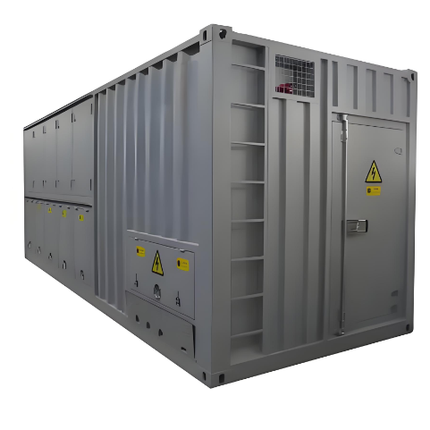
• 10.5KV 2500kW High Voltage Load Bank for Generator Test
10.5KV 2500kW High Voltage Load Bank for Generator Test
discuss personally
Model
LB-10.5/2500
Basic info
Brand Wone
Model NO. 10.5KV 2500kW High Voltage Load Bank for Generator Test
Rated voltage 10.5KV
Power 2500KW
Series LB
Product Detail

Deacription

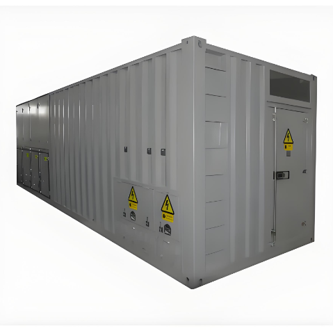
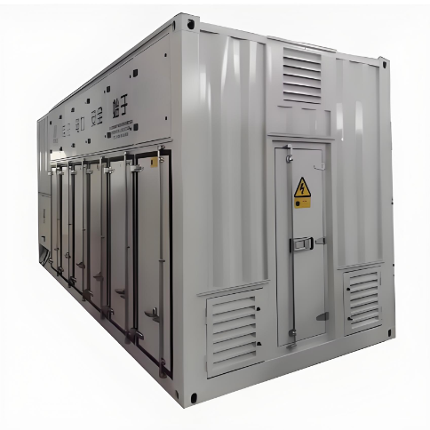
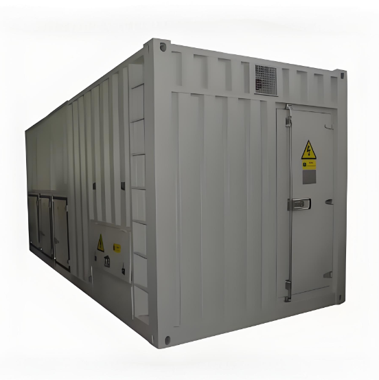
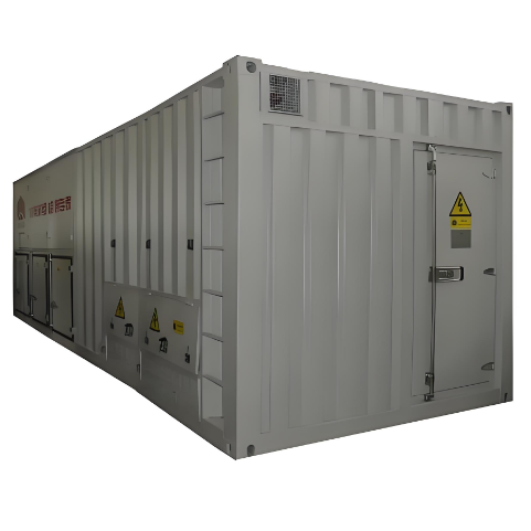
Intelligent AC load bank main used to test the capability and aging degree for high-power ups on-line, inverter, switch power and diesel generator set for electric power, telecom department and manufacturer. It can ensure the reliability of constant power charge that adopts uniformly stepped power input, energy consumption work model and forced air-cooling model. It is of high power density, no red hot phenomenon and automatic protection function overheated. It can’t be overheated and broken when the fans stop working. The complete machine can be operated simply and maintain convenient that adopts module design. It can test voltage and current according to client’s request, and provide scientific test measures for high-power AC equipment.

Feature

  •  Users can set adjustable discharge power according to capability parameter and test request.

  • Voltage and current value can be displayed with multi-functional digital meter.

  • AC load bank is of all kinds of specifications and series, and include resistance, inductive and capacitive load.

  •  Two or more Intelligent AC Load Bank can operate in parallel.

  •  It can make stable state test. 

  •  Remote control by software.

  •  Testing data can be saved or transferred by RS485, data can form curve, to be printed. 


Parameter

image.png


Function options

  • Intelligent AC Load Bank has two control patterns: position machine software control and local panel control

  • Intelligent AC load bank (LED): multi-function digital special meter of 0.5 step can be test and display: AC voltage, current, active power, power factor and frequency. It can communicate with PC via RS485 interface.

  • Intelligent AC load bank (LCD): Special LCD meter display: AC voltage, current, active power, power factor and voltage frequency. It is of the harmonic analysis function of 1-40 times, and can communicate with PC via RS485 interface.


Know your supplier
Wone
Main Categories
High voltage/Low voltage/Wire cable/Instrument meters/New energy/Tester/Production equipment/Generator/Electrical fittings/Integrated Electrical Equipment
Business Type
Design/Manufacture/Sales
Highest Annual Export (USD)
$50,000,000
Professional Experience
1 years
Workplace
65666m²m²
占位
占位
Related Products
Related Knowledges
Failure Analysis and Design Optimization of Conventional Grounding Transformers
I. Core Cause of Damage: Electrodynamic Impact (Complying with GB/T 1094.5 / IEC 60076-5)The direct cause of high-voltage winding end collapse is the instantaneous electrodynamic impact induced by short-circuit current. When a single-phase grounding fault occurs in the system (such as lightning overvoltage, insulation breakdown, etc.), the grounding transformer, as the fault current path, withstands high-amplitude and steep-rise-rate short-circuit currents. According to Ampère's force law
Felix Spark
06/12/2025
Analysis of Grounding Transformer Operational Behavior Under System Single-Phase-to-Ground Fault Conditions
1 Theoretical AnalysisIn distribution networks, grounding transformers serve two key roles: powering low - voltage loads and connecting arc - suppression coils at neutrals for grounding protection. Grounding faults, the most common distribution network fault, heavily impact transformers’ operating characteristics, causing sharp changes in electromagnetic parameters and status.To study transformers’ dynamic behaviors under single - phase grounding faults, build this model: Assume a tr
Felix Spark
06/12/2025
Design Calculations for Neutral Grounding Schemes and Grounding Transformer Sizing in Utility-Scale Solar PV Plants
1 Classification of Neutral Grounding Methods for Solar Photovoltaic Power StationsInfluenced by differences in voltage levels and grid structures across regions, the neutral grounding methods of power systems are mainly categorized into non-effective grounding and effective grounding. Non-effective grounding includes neutral grounding via arc suppression coils and neutral ungrounded systems, while effective grounding comprises neutral solid grounding and neutral grounding via resistors. The sel
Dyson
06/12/2025
Zero-Sequence Impedance Characterization of Dry-Type Grounding Transformer with ZN Connection
In a neutral-insulated three-phase power system, an earthing transformer provides an artificial neutral point, which can be solidly earthed or earthed via reactors/arc suppression coils. The ZNyn11 connection is typical, where zero-sequence magnetomotive forces in the inner/outer half-windings of the same core column cancel out, balancing fault currents in series windings and minimizing zero-sequence leakage flux/impedance.Zero-sequence impedance is critical: it determines fault current magnitud
Dyson
06/12/2025
Case Analysis on Maloperation of Grounding Transformer Overcurrent Protection Relay
The neutral grounding mode refers to the connection between the power system neutral point and ground. In China's 35 kV and below systems, common methods include ungrounded neutral, arc-suppression coil grounding, and small-resistance grounding. The ungrounded mode is widely used as it allows short-term operation during single-phase grounding faults, while small-resistance grounding has become mainstream for its fast fault removal and overvoltage limitation. Many substations install grounding tr
Felix Spark
06/12/2025
Discussion on the Design of Low Zero-Sequence Impedance Grounding Transformers
With the expansion of power system scale and the cableization process of urban power grids, the capacitive current in 6kV/10kV/35kV power grids has significantly increased (generally exceeding 10A). As power grids at this voltage level mostly adopt neutral ungrounded operation mode, and the distribution voltage side of main transformers is usually in delta connection, lacking a natural grounding point, the arc during ground faults cannot be reliably extinguished, necessitating the introduction o
Dyson
06/11/2025
×
Inquiry
Download
Experts Electrical is dedicated to serving the personnel in the global power industry.
Join Experts Electrical, not only can you discover power equipment and power knowledge, but also canhnd like - minded friends!
商品视频播放