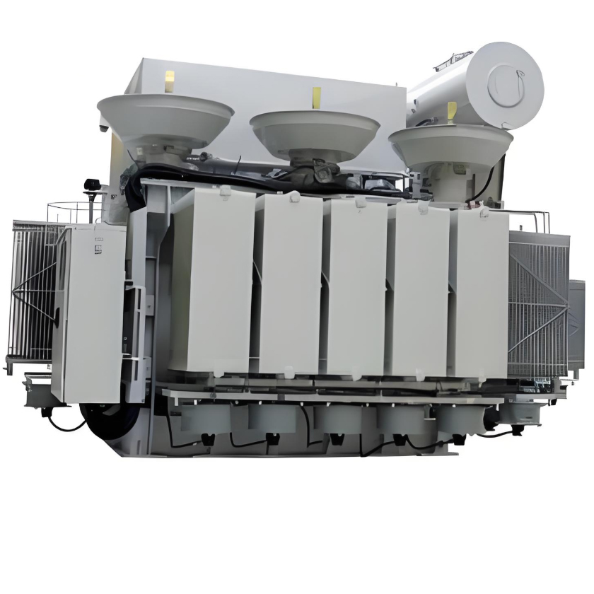
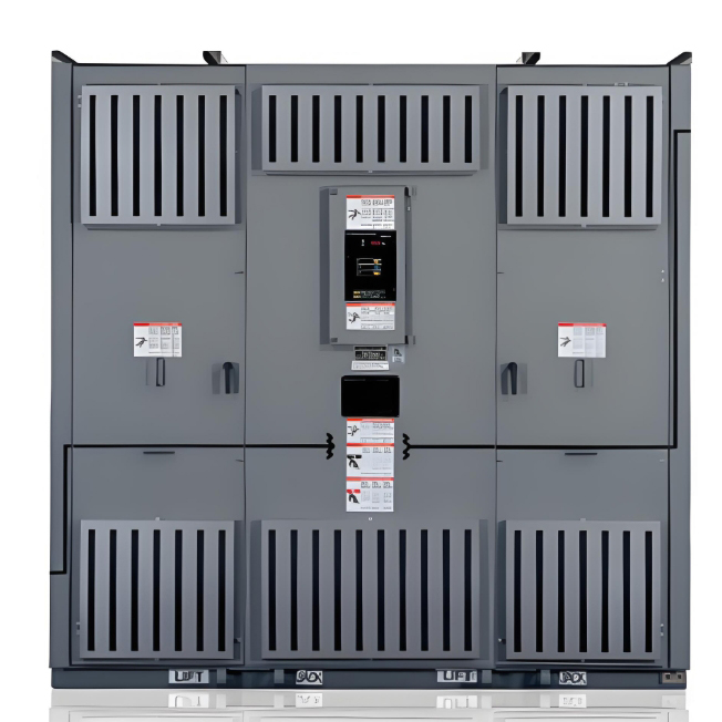
Energy Efficient Medium Voltage Transformers
discuss personally
Model
| Brand | Schneider |
| Model NO. | Energy Efficient Medium Voltage Transformers |
| Phases | 三相 |
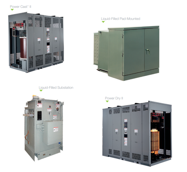
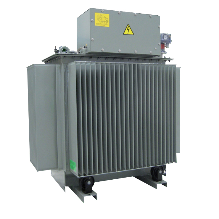
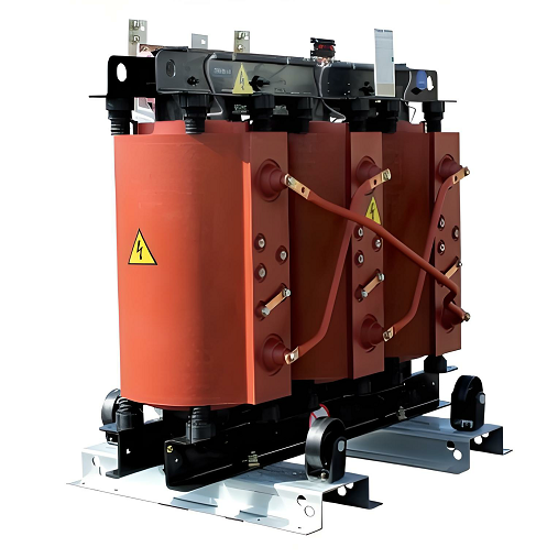
| Series | Liquid-Filled /Power Dry |
General
Features and Benefits
Environmental Impact
According to the DOE (10 CFR Part 431), these new standards provide significant
benefits to the nation.
Saves 2.74 quads (1,015 BTUs) of energy over 29 years
Technical characteristics
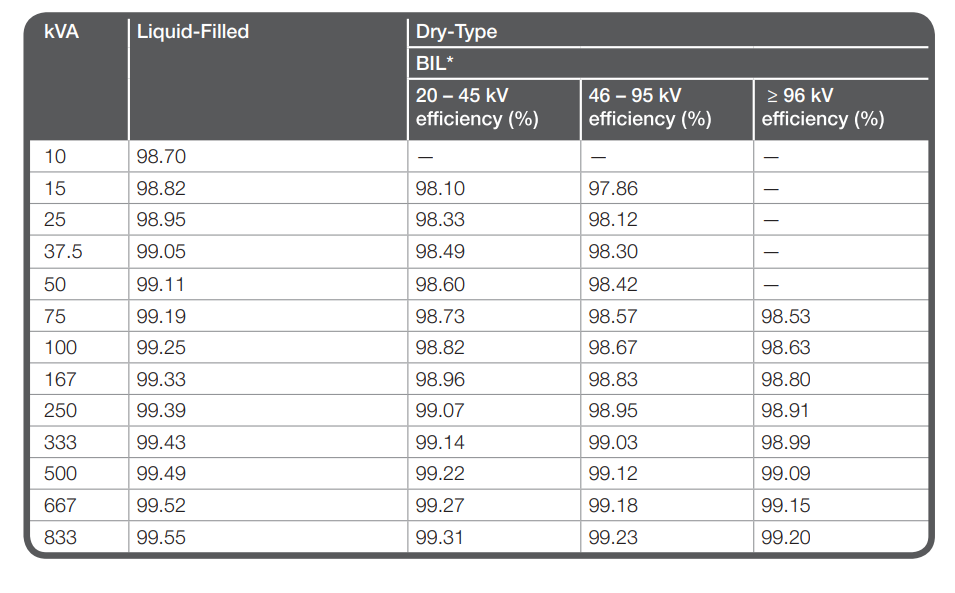
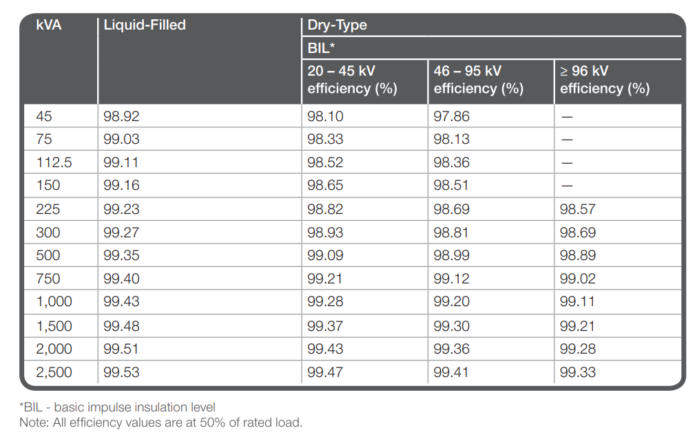
New Medium Voltage Transformer Efficiencies
Single phase
Three phase
Medium Voltage Transformers