What is the Circle Diagram of Induction Motor ?
What is the Circle Diagram of Induction Motor ?
Circle Diagram Definition
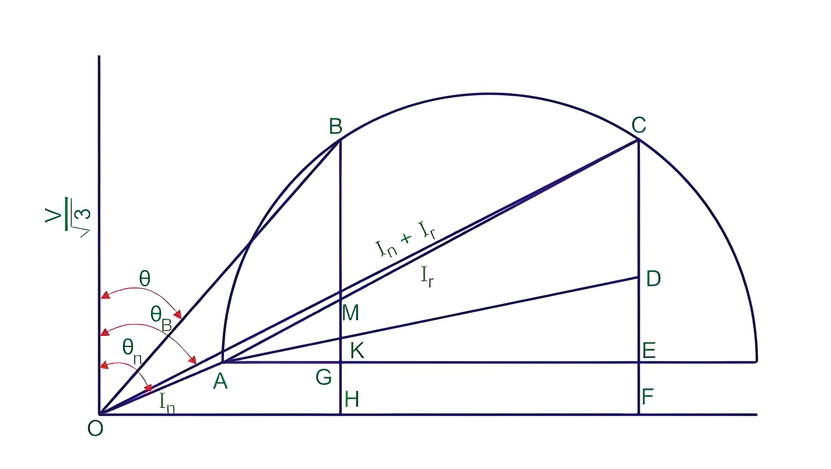
A circle diagram is a graphical tool used to represent the performance of electrical machines like induction motors.
Importance of Circle Diagram
It provides a comprehensive view of various performance parameters, unlike a phasor diagram which only shows current and voltage for a single condition.
Tests for Data Collection
The no-load and blocked rotor tests are essential for gathering data to draw the circle diagram of an induction motor.
Steps to Draw Circle Diagram
This involves plotting no-load and short circuit currents, finding the center, and drawing lines to determine power and torque.
Parts of a Circle Diagram
Key parts include lines and points that represent maximum output power, torque, and input power.
Conclusion of Circle Diagram
This method uses some approximations and rounding off values to draw the circle diagram. Despite these errors, it still provides a good estimate of the results.The main downside to a circle diagram is that although it is easy to interpret and read, it can be quite time consuming to draw. Alternative methods include using mathematical formulas or equivalent circuit models instead to find out the various performance parameters. If you’re looking to learn more about circle diagrams and other electrical engineering topics, check out our full list of basic electrical questions.
The Electricity Encyclopedia is dedicated to accelerating the dissemination and application of electricity knowledge and adding impetus to the development and innovation of the electricity industry.
