Induction Motor Braking
Braking of Induction Motor
Induction motors are used in many applications. Speed control of induction motors is difficult, which initially limited their use, favoring DC motors instead. However, the invention of induction motor drives highlighted their advantages over DC motors. Braking is crucial for controlling motors, and induction motors can be braked using various methods, including:
Regenerative braking of induction motor
Plugging Braking of induction motor
Dynamic braking of induction motor is further categorized as
AC dynamic breaking
Self excited braking using capacitors
DC dynamic braking
Zero Sequence braking
Regenerative Braking
We know the power (input) of an induction motor is given as.
Pin = 3VIscosφs
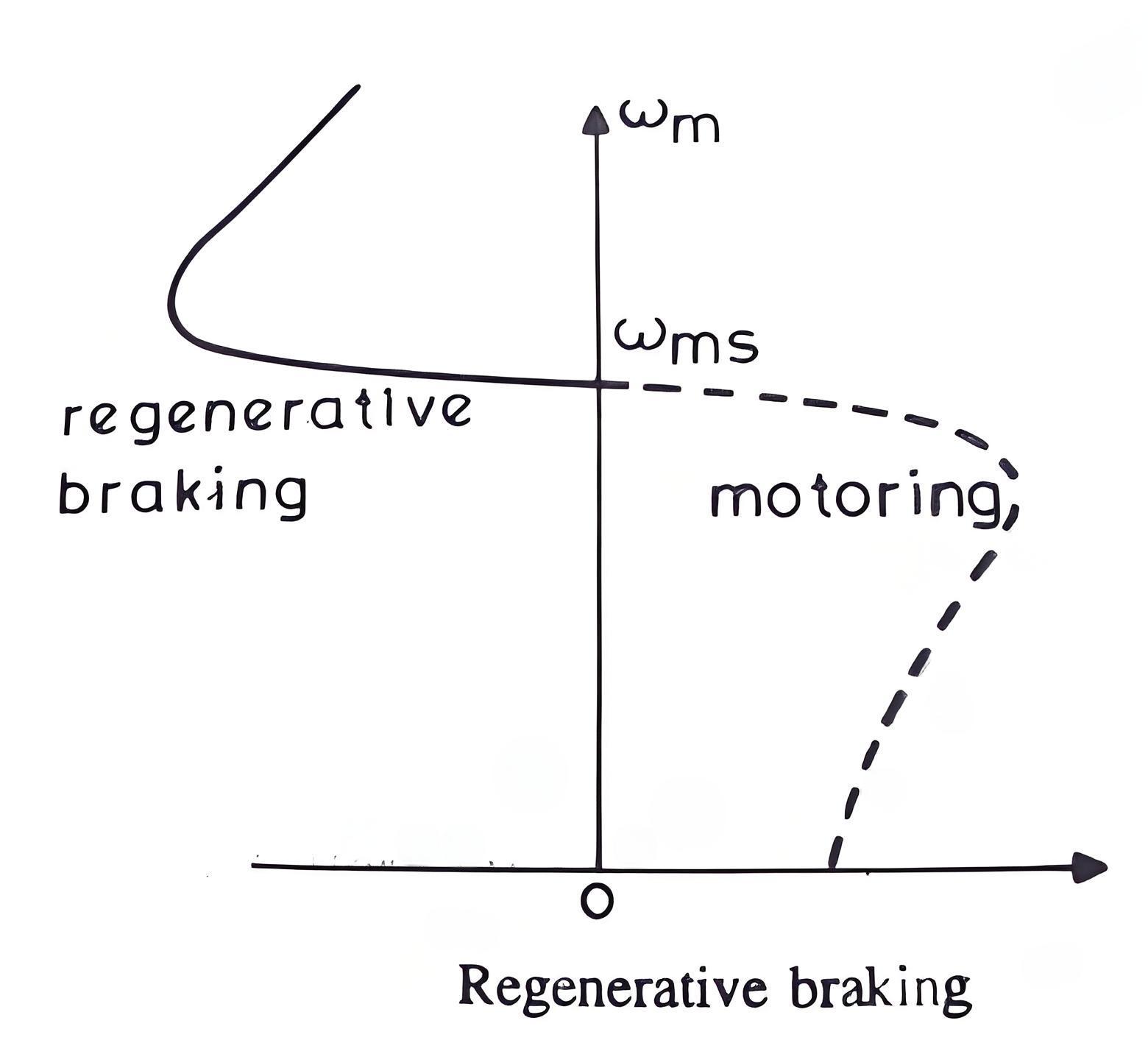
Here, φs the phase angle between stator phase voltage V and the stator phase current Is. Now, for motoring operation φs < 90o and for braking operation φs > 90o. When the speed of the motor is more than the synchronous speed, relative speed between the motor conductors and air gap rotating field reverses, as a result the phase angle because greater than 90o and the power flow reverse and thus regenerative braking takes place. The nature of the speed torque curves are shown in the figure beside. It the source frequency is fixed then the regenerative braking of induction motor can only take place if the speed of the motor is greater than synchronous speed, but with a variable frequency source regenerative braking of induction motor can occur for speeds lower than synchronous speed. The main advantage of this kind of braking can be said that the generated power is use fully employed and the main disadvantage of this type of braking is that for fixed frequency sources, braking cannot happen below synchronous speeds.
Plugging Braking
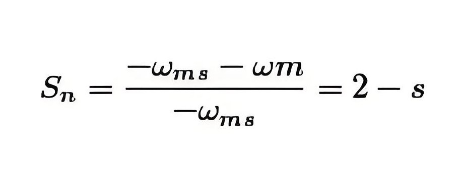
Plugging induction motor braking is done by reversing the phase sequence of the motor. Plugging braking of induction motor is done by interchanging connections of any two phases of stator with respect of supply terminals. And with that the operation of motoring shifts to plugging braking. During plugging the slip is (2 – s), if the original slip of the running motor is s, then it can be shown in the following way.
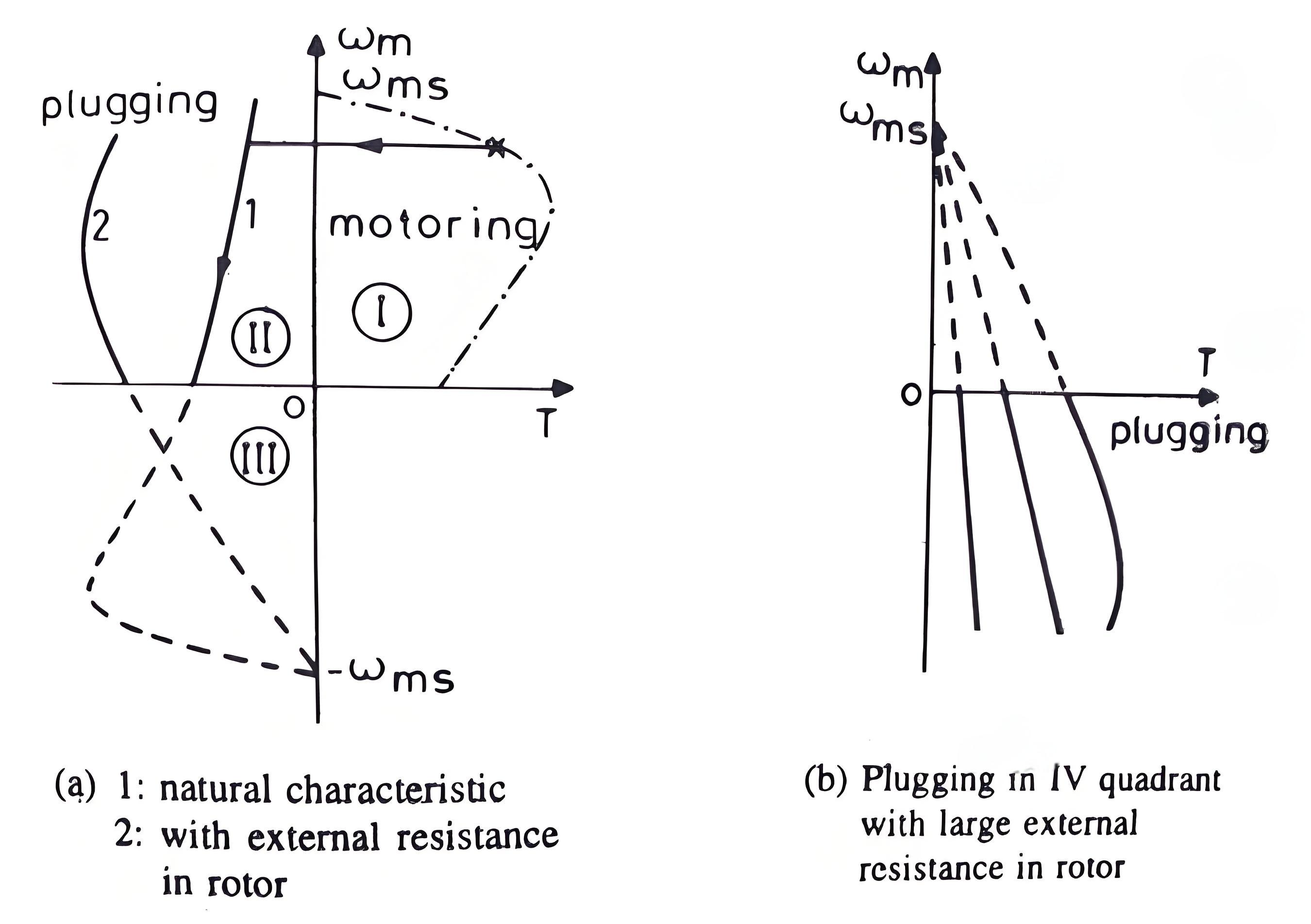
From the figure beside we can see that the torque is not zero at zero speed. That’s why when the motor is needed to be stopped, it should be disconnected from the supply at near zero speed. The motor is connected to rotate in the reverse direction and the torque is not zero at zero or any other speed, and as a result the motor first decelerates to zero and then smoothly accelerates in the opposite direction.
AC Dynamic Braking
Involves disconnecting one phase, allowing the motor to run on a single phase, creating braking torque due to positive and negative sequence voltages.
Self Excited Braking
Uses capacitors to excite the motor when disconnected from the source, turning it into a generator and producing braking torque.
The Electricity Encyclopedia is dedicated to accelerating the dissemination and application of electricity knowledge and adding impetus to the development and innovation of the electricity industry.
