Abnormal Operating Condition and Causes of Induction Motors

Edwiin
05/19/2025
Abnormal Supply Conditions
Internal Motor Faults
Topics
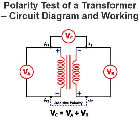
Polarity Test of a Transformer – Circuit Diagram and Working
Polarity in Two-Winding TransformersIn two-winding transformers, one terminal of a winding is always positive relative to the other at any instant. Transformer polarity refers to therelative direction of induced voltagesbetween the high-voltage (HV) and low-voltage (LV) windings. In practical transformers, winding terminals are brought out as leads, and polarity defines how these leads are connected and labeled.Significance of Transformer PolarityUnderstanding polarity is critical for several op
Edwiin
05/15/2025
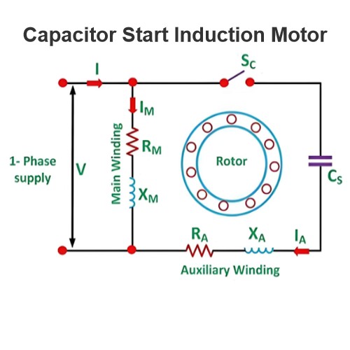
Capacitor Start Induction Motor
Capacitor Start Motors are a type of single - phase induction motors. They utilize a capacitor within the auxiliary winding circuit to create a significant phase difference between the current flowing through the main winding and that in the auxiliary winding. As the name "capacitor start" clearly implies, these motors rely on a capacitor specifically for the starting process. The diagram below illustrates the connection schematic of a Capacitor Start Motor.The capacitor start motor features a c
Encyclopedia
05/09/2025
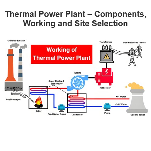
Thermal Power Plant – Components, Working and Site Selection
What is a Thermal Power Plant?The law of energy conservation states that energy cannot be created or destroyed; rather, it can only be transformed from one form to another. Electrical energy, in particular, can be harnessed from a variety of energy sources. Facilities designed to generate large - scale electrical energy are commonly referred to as power plants or power stations.A thermal power plant is a type of power generation facility that converts heat energy into electrical energy. Heat ene
Encyclopedia
05/07/2025
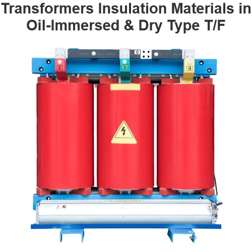
Transformers Insulation Materials in Oil-Immersed & Dry Type T/F
Insulation in Oil-Immersed TransformersIn contemporary oil - immersed transformers, the insulation of high - voltage windings follows a widely adopted approach. Typically, the wire is coated with enamel, and kraft paper is inserted between each layer of the winding. This combination provides reliable electrical insulation and mechanical protection for the high - voltage windings, safeguarding them against electrical breakdown and physical damage.For low - voltage windings, a different insulation
Encyclopedia
05/07/2025


