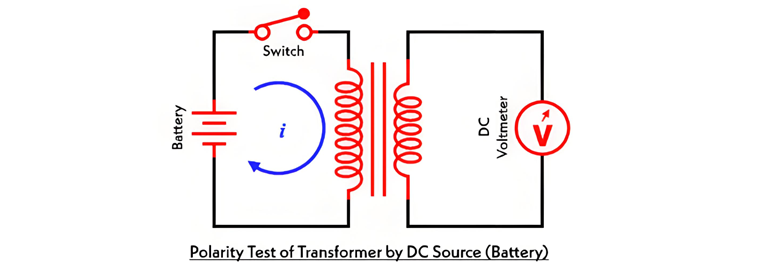
Polarity Test of a Transformer – Circuit Diagram and Working

Edwiin
05/15/2025
Terminal Markings and Polarity Identification
Key Consideration

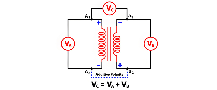
The circuit diagram of additive polarity is shown in the figure below.
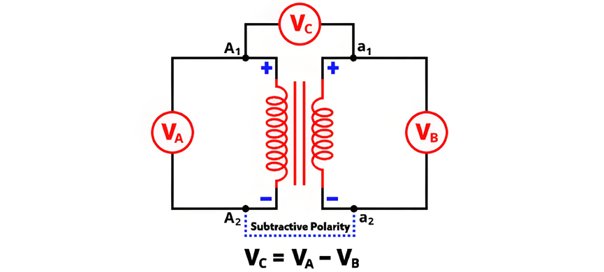
Subtractive Polarity

Topics
What are the criteria for selection of distribution transformer?
Transformer Selection Criteria: Essential Factors for Optimal PerformanceSelecting the appropriate transformer is critical for ensuring power distribution reliability across industrial, commercial, and residential systems. This process requires meticulous evaluation of load dynamics, environmental constraints, and regulatory standards. Below we outline key selection criteria to guide engineers and designers in making informed decisions.1. Maximum Demand AssessmentThe transformer’s capacity (kVA)
Master Electrician
07/03/2025

In which directions will dry-type transformers develop in the future?
By Echo, 12 Years in the Electrical IndustryHi everyone, I'm Echo, and I've been working in the electrical industry for 12 years.From my early days doing commissioning and maintenance in distribution rooms, to later participating in electrical system design and equipment selection for large-scale projects, I’ve witnessed how dry-type transformers have evolved from traditional tools into smarter, greener devices.Recently, a new colleague asked me:“What’s the current state of dry
Echo
07/02/2025
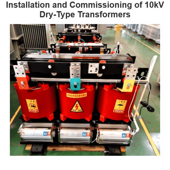
Installation and Commissioning of 10kV Dry-Type Transformers
By James, 10 Years of Electrical Equipment Maintenance ExperienceHi everyone, I’m James, and I’ve been working in electrical equipment fault repair for 10 years.Over the past decade, I’ve worked in factories, substations, and distribution rooms of all sizes, involved in the installation, commissioning, maintenance, and troubleshooting of dry-type transformers. Dry-type transformers are among the most common electrical devices we deal with on a daily basis.Today, a new colleague
James
07/01/2025
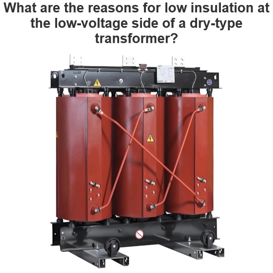
What are the reasons for low insulation at the low-voltage side of a dry-type transformer?
Hi everyone, I’m Felix, and I’ve been working in electrical equipment fault repair for 15 years.Over these years, I’ve traveled across factories, substations, and distribution rooms all over the country, troubleshooting and repairing all kinds of electrical equipment. Dry-type transformers are among the most common devices we deal with.Today, a friend asked me:“What does it mean when the low-voltage side of a dry-type transformer has low insulation resistance?”Great
Felix Spark
07/01/2025


