Rating of Alternator
Electrical4u
05/07/2024

image.png

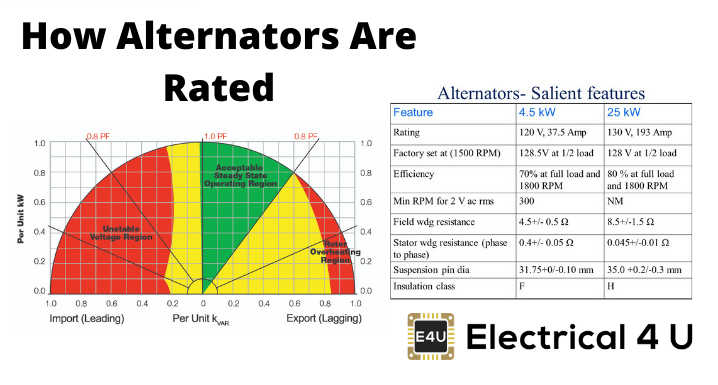
Power rating of an alternator is defined as the power which can be delivered by an alternator safely and efficiently under some specific conditions. Increasing load increases losses in the alternator, which leads to a temperature rise of the machine. The conductor and insulator parts of the machine have some specific overheating withstand limits. The manufacturer so specifies the power rating of an alternator that at that maximum load the temperature rise of different parts of the machine does not cross their specified safe limit.

The copper losses i.e. I2R loss varies with armature current and core losses vary with voltage. The temperature rise or heating of alternator depends upon cumulative effect of copper losses and core losses. As there is no role of power factor upon these losses, the rating of alternator generally given in the order of VA or KVA or MVA.
In other words, as the losses of the alternator are independent of electrical power factor, hence power factor does not come into picture while we calculate and estimate the power rating of an alternator. Although losses of the alternator depend upon its KVA or MVA rating, actual output varies with electrical power factor.

The electrical output of an alternator is a product of power factor and VA. We express the output in KW.
Sometimes alternators are also rated by its power instead of VA rating. That time electrical
power factor of the alternator must be specified too.
In addition to KVA rating, an alternator has also
voltage, electric current, frequency, speed, number of phases, number of poles, field ampere, excitation voltage, maximum temperature rise limit ratings, etc.
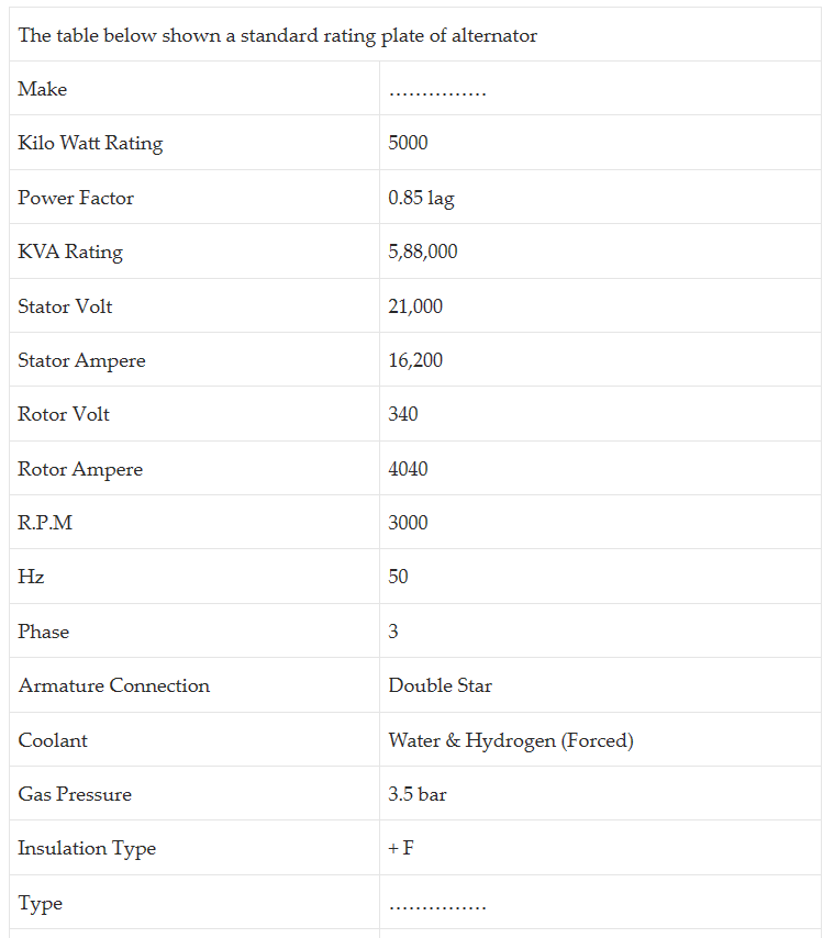
image.png

image.png

Statement: Respect the original, good articles worth sharing, if there is infringement please contact delete.    

Electrical4u

Electrical4U is dedicated to the teaching and sharing of all things related to electrical and electronics engineering.
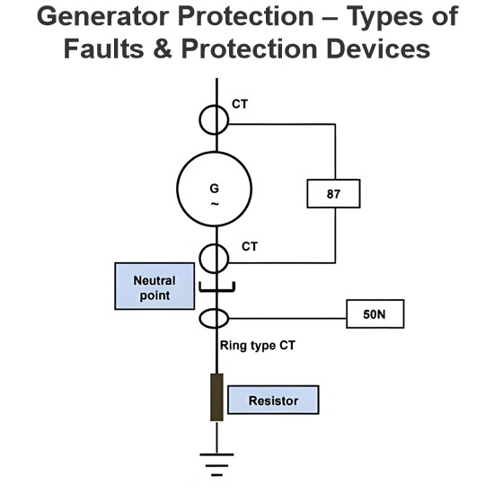
Generator Protection – Types of Faults & Protection Devices
Common Generator Faults and Protection SystemsClassification of Generator FaultsGenerator faults are primarily categorized into internal and external types:Internal Faults: Arise from issues within generator components.External Faults: Stem from abnormal operating conditions or external network issues.Faults in prime movers (e.g., diesel engines, turbines) are mechanical in nature and defined during equipment design, though they must integrate with generator protections for tripping purposes.Typ
Edwiin
06/05/2025
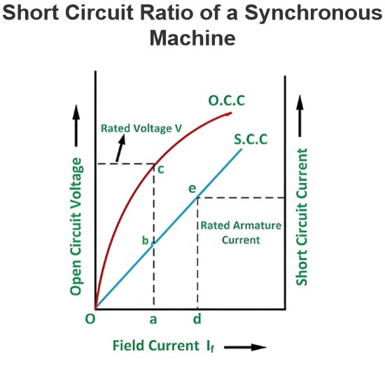
Short Circuit Ratio of a Synchronous Machine
The Short Circuit Ratio (SCR) of a Synchronous MachineThe Short Circuit Ratio (SCR) of a synchronous machine is defined as the ratio of the field current needed to generate rated voltage under open-circuit conditions to the field current required to sustain rated armature current during a short-circuit condition. For a three-phase synchronous machine, the SCR can be derived from its Open-Circuit Characteristic (O.C.C) at rated speed and Short-Circuit Characteristic (S.C.C), as illustrated in the
Edwiin
06/04/2025
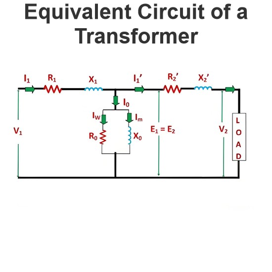
Equivalent Circuit of a Transformer
The equivalent circuit diagram of any device can be extremely useful for predicting how the device will behave under different operating conditions. It is essentially a circuit - based depiction of the equations that describe the device's performance.The simplified equivalent circuit of a transformer is constructed by representing all of the transformer's parameters on either the secondary side or the primary side. The equivalent circuit diagram of the transformer is presented below:Let the equi
Edwiin
06/03/2025
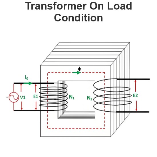
Transformer On Load Condition
Transformer Operation Under Load ConditionsWhen a transformer is under load, its secondary winding connects to a load, which can be resistive, inductive, or capacitive. A current I2 flows through the secondary winding, with its magnitude determined by the terminal voltageV2and load impedance. The phase angle between the secondary current and voltage depends on the load characteristics.Explanation of Transformer Load OperationThe operational behavior of a transformer under load is detailed as fol
Edwiin
06/03/2025
Inquiry
Download
Experts Electrical is dedicated to serving the personnel in the global power industry.
Join Experts Electrical, not only can you discover power equipment and power knowledge, but also canhnd like - minded friends!