Interfacing of a Stepper Motor
Stepper Motor Definition
A stepper motor is a DC motor that moves in steps, with rotation speed dependent on the electrical signal rate.
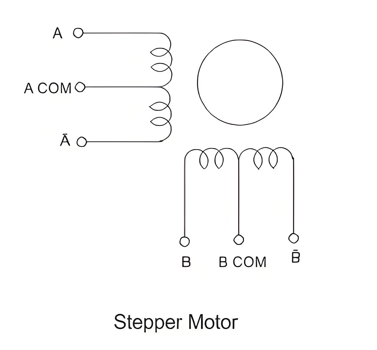
Components
The motor has a rotor (permanent magnet) and a stator (winding), with the rotor rotating and the stator stationary.
Working Principle
The center tap on the stator winding allows current direction change when grounded. This changes the stator’s magnetic properties, selectively attracting and repelling the rotor to create a stepping motion.
Stepping Sequence
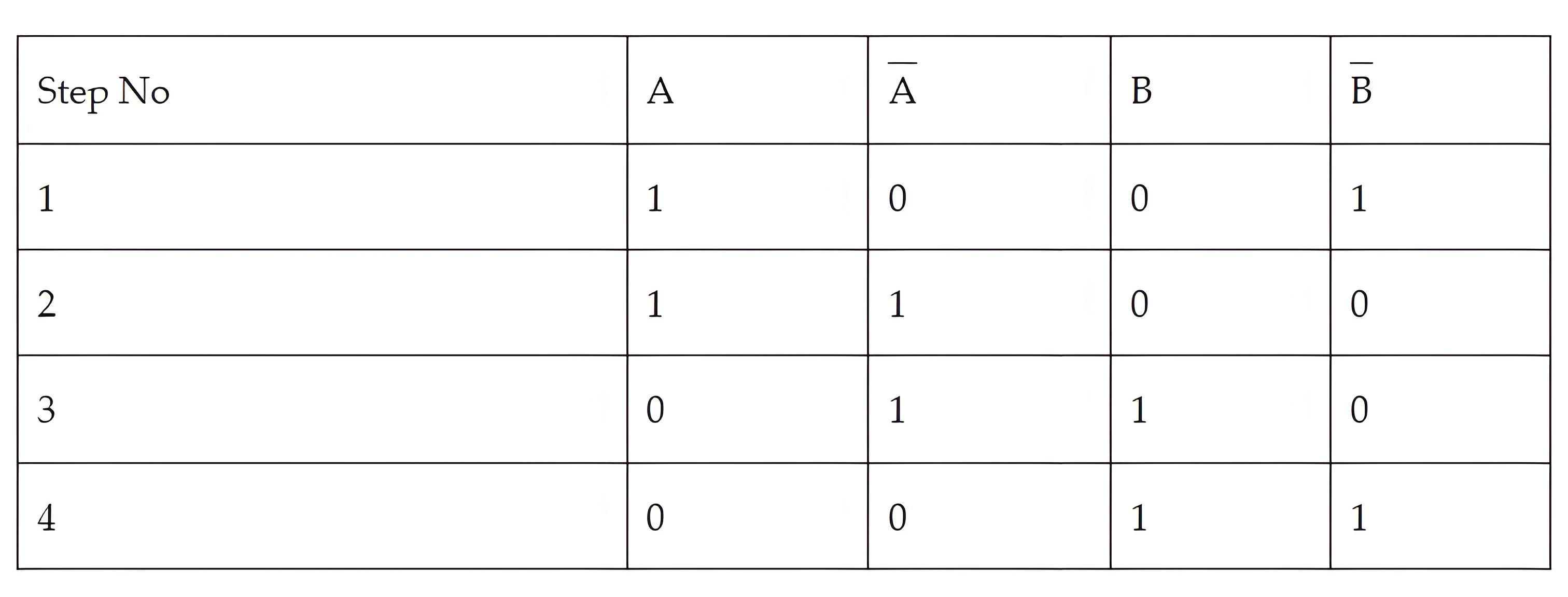
In order to get correct motion of the motor, a stepping sequence has to be followed. This stepping sequence gives the voltage that must be applied to the stator phase. Normally a 4 step sequence is followed.
When the sequence is followed from step 1 to 4, we get a clock wise rotation and when it is followed from step 4 to 1, we get a counter clockwise rotation.
Interfacing Diagram
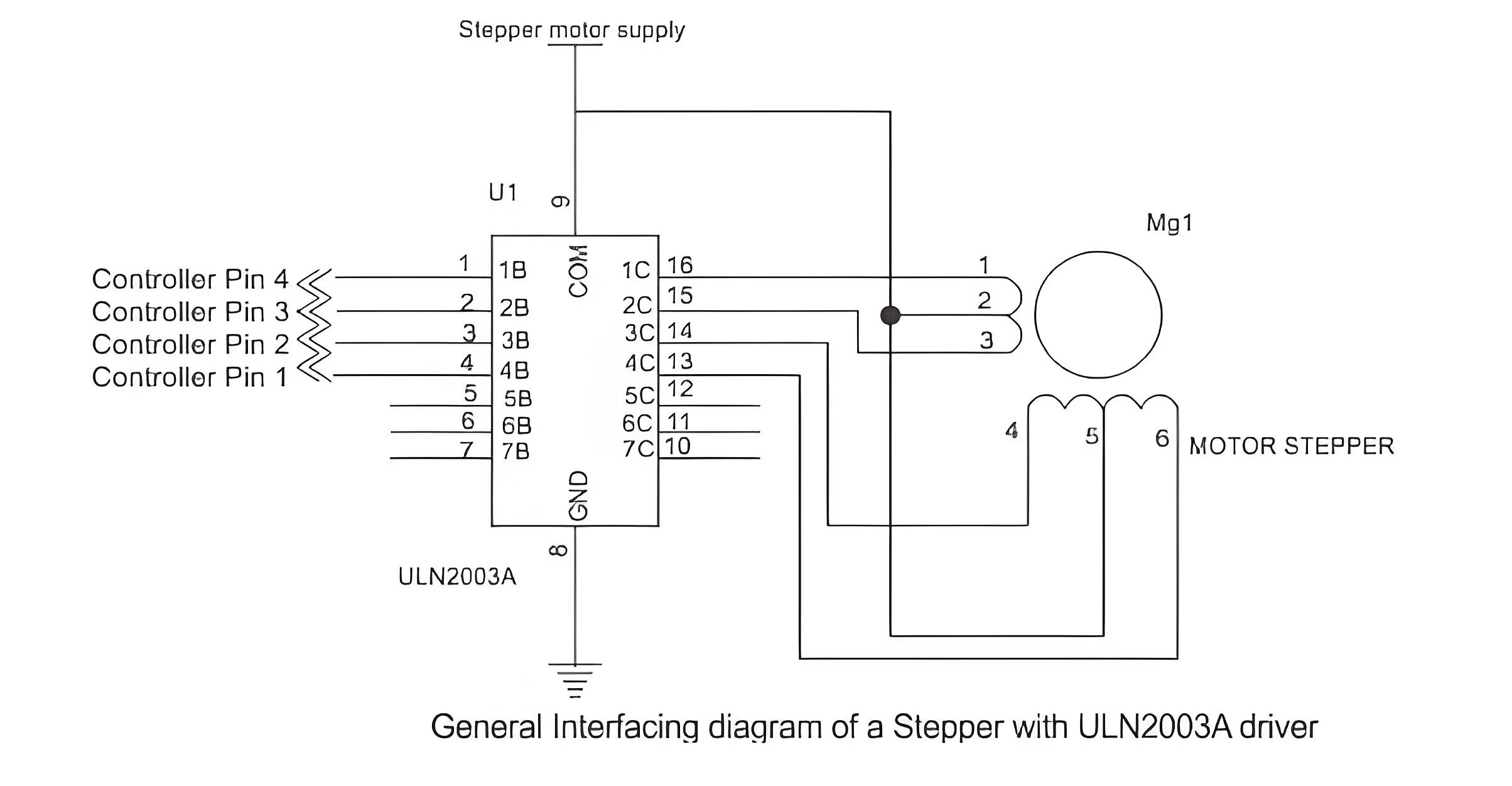
The diagram below shows the interfacing of stepper motor to a micro-controller. This is general diagram and can be applied to any micro-controller family like PIC micro-controller, AVR or 8051 micro-controller.
Since the microcontroller cannot provide enough current, a driver like ULN2003 is used to run the motor. Individual transistors or other driver ICs can also be used. Ensure external pull-up resistors are connected if needed. Never connect the motor directly to the controller pins. The motor voltage depends on its size.
A typical 4 phase uni-polar stepper motor has 5 terminals. 4 phase terminals and one common terminal of the center tap that is connected to ground. The programming algorithm for continuous rotation in clockwise mode is given below-
Initialize the port pins used for the motor as outputs
Write a common delay program of say 500 ms
Output first sequence-0 × 09 on the pins
Call delay function
Output second sequence-0 × 0 c on the pins
Call delay function
Output third sequence-0 × 06 on the pins
Call delay function
Output fourth sequence-0 × 03 on the pins
Call delay function
Go to step 3
Step Angle
The number of steps required to complete one full rotation depends on the step angle of the stepper motor. The step angle can vary from 0.72 degrees to 15 degrees per step. Depending on that 500 to 24 steps may be required to complete one rotation. In position control applications the selection on motor should be based on the minimum degree of rotation that is required per step.
Half Stepping
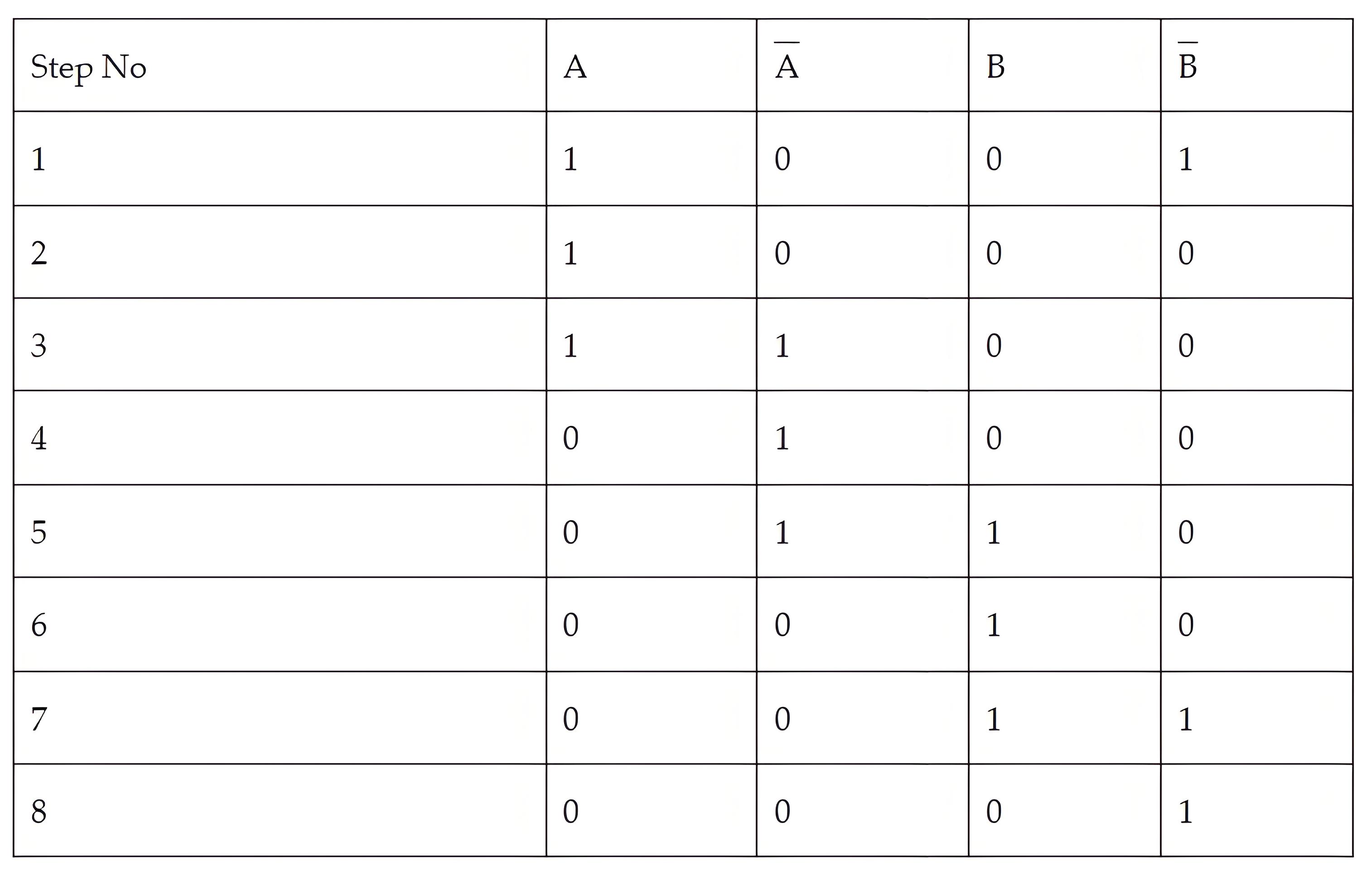
Stepper motors can operate at half the actual step angle, known as half stepping. For example, a motor rated for 15 degrees per step can be programmed to rotate at 7.5 degrees per step using a special half-stepping sequence.
Stepper Motor v/s Servo Motor
Both the stepper motor and servo motor are used primarily in position control applications. But there lies a difference in their working and construction. The stepper motor has a large number of poles or teeth on their rotor and these teeth act as magnetic north and south poles which gets attracted or repelled to the electrically magnetized coil of the stator. This helps in the stepping motion that a stepper generates.
On the other hand, in a servo motor the position is controlled by the specialized circuit and the feedback mechanism, which generates an error signal to move the motor shaft.
The Electricity Encyclopedia is dedicated to accelerating the dissemination and application of electricity knowledge and adding impetus to the development and innovation of the electricity industry.

