What is a DC Motor Drive?
What is a DC Motor Drive?
DC Motor Drives Definition
DC motor drives are systems used to control the performance of DC motors, enhancing operations such as speed, starting, braking, and reversing.
Starting Mechanisms
Starting DC motor drives involves managing high initial currents to prevent motor damage, typically by varying resistance.
Braking Systems
Braking is a very important operation for DC motor drives. The need of decreasing the speed of a motor or stopping it totally may arise at any moment, that’s when braking is applied. braking of DC motors is basically developing a negative torque while the motor works as generator and as a result the motion of the motor is opposed. There are mainly three types of braking of DC motors :
Regenerative braking
Takes place when the generated energy is supplied to the source, or we can show this via this equation :
E > V and negative Ia.
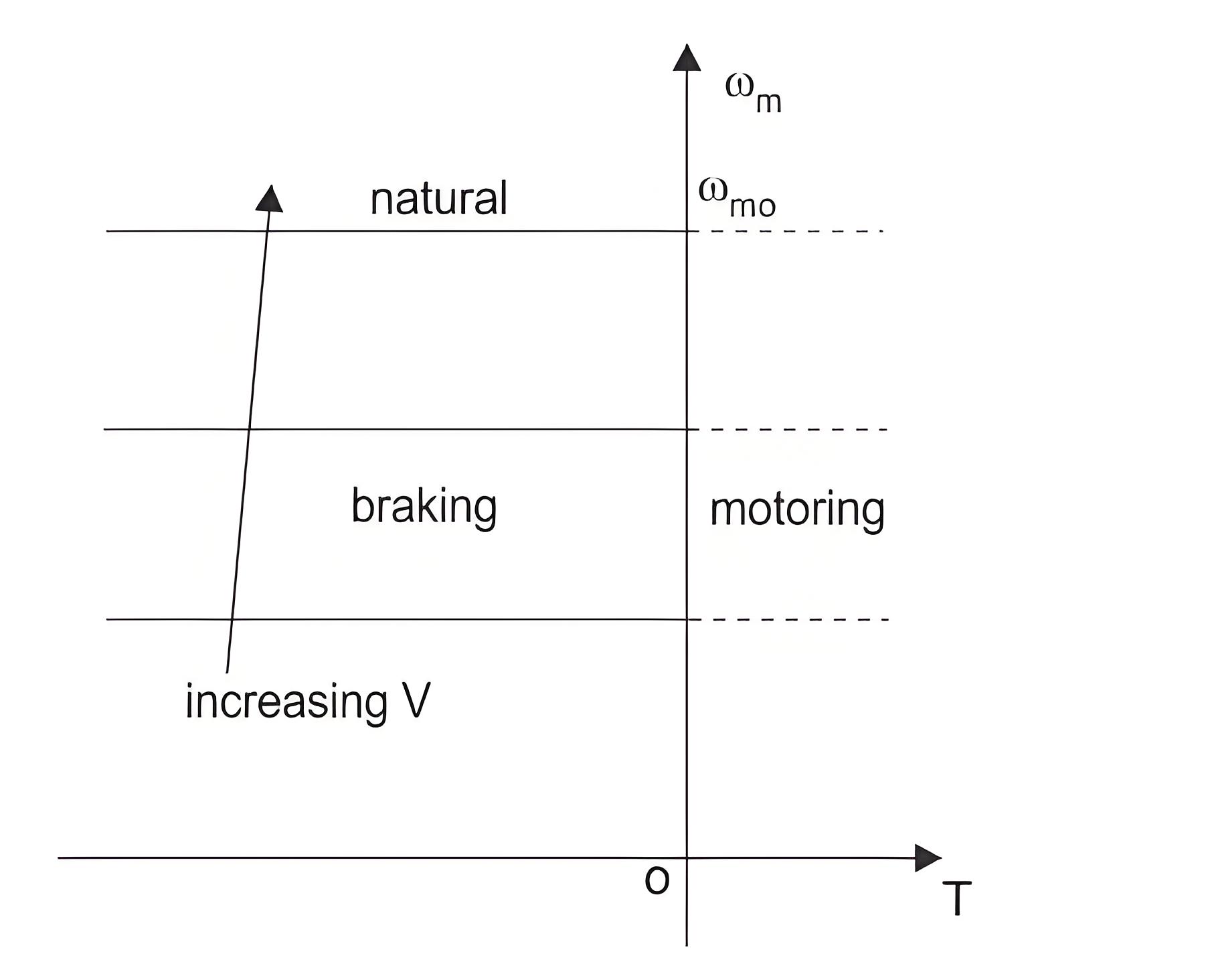
As the field flux cannot be increased beyond a rated value, so regenerative braking is possible only when the speed of motor is higher than the rated value. The speed torque characteristics is shown in the graph above. When regenerative braking occurs, the terminal voltage rises and as a result the source is relieved from supplying this amount of power. This is the reason why loads are connected across the circuit. So, it is clear that regenerative braking should be used only when there are enough loads to absorb the regenerative power.
Dynamic or rheostat braking
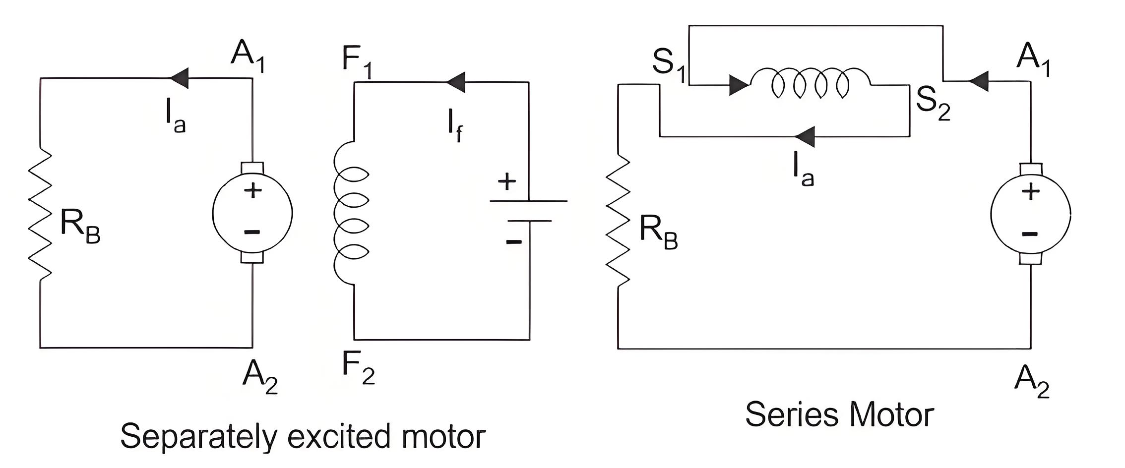
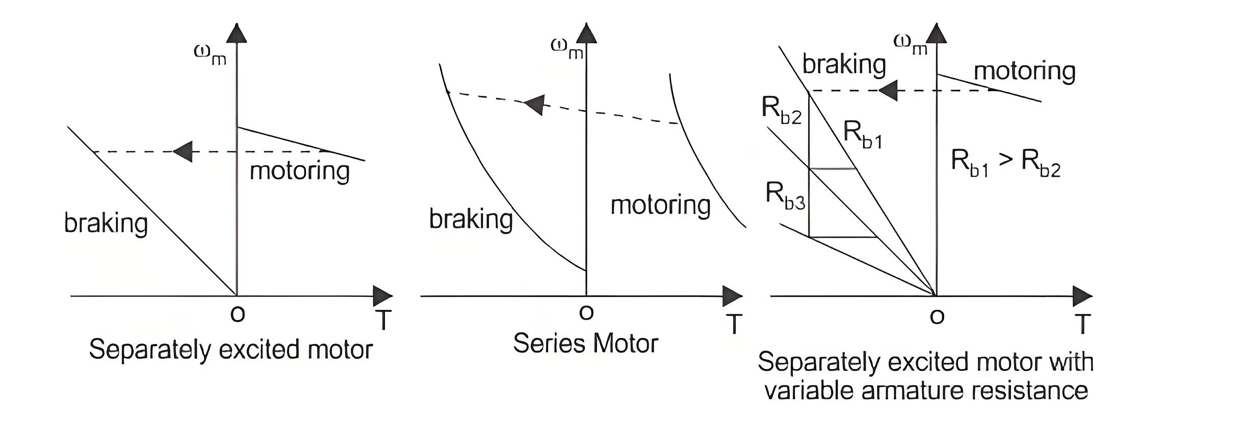
Dynamic Braking is another type of braking of DC motor drives where the rotation of the armature itself causes the braking. This method is also a widely used DC motor drive system. When braking is desired, then the armature of the motor is disconnected from the source and a series resistance is introduced across the armature. Then the motor acts as a generator and current flows in the opposite direction which indicates that the field connection is reversed. The diagram for separately excited and series DC motor both are shown in figure below.
When braking is required to occur quickly the resistance (RB) is considered to be of some sections. As the braking occurs and the speed of the motor falls, the resistance are cut out one by one section to maintain the light average torque.
Plugging or reverse voltage braking.
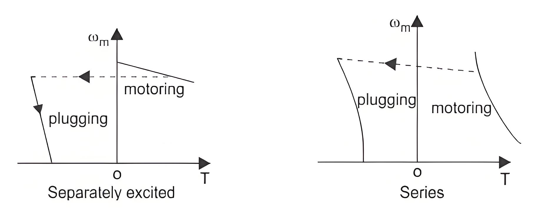
Plugging is a type of braking where the supply voltage is reserved when the need of braking arises. A resistance is also introduced in the circuit while braking takes place. When the direction of the supply voltage is reserved, then the armature current also reserves forcing the back enf to a very high value and hence braking the motor. For series motor only armature is reversed for plugging. The diagram of separately excited and series excited motors are shown in the figure.

Speed Control
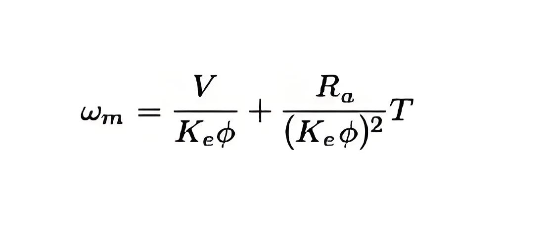
The main application of electric drives can be said as the need of braking of DC motors . We know the equation to describe the speed of a rotating DC motor drives is as
Now, according to this equation, the speed of a motor can be controlled by the following methods
Armature voltage control
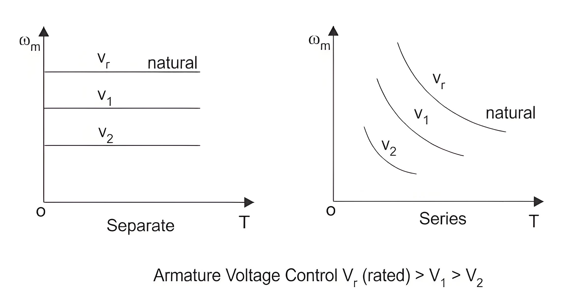
Among all of these, armature voltage control is preferred because of high efficiency and good speed regulation and good transient response. But the only disadvantage of this method is that it can only operate under the rated speed, because the armature voltage cannot be allowed to exceed rated value. The speed torque curve for armature voltage control is shown below.
Field flux control
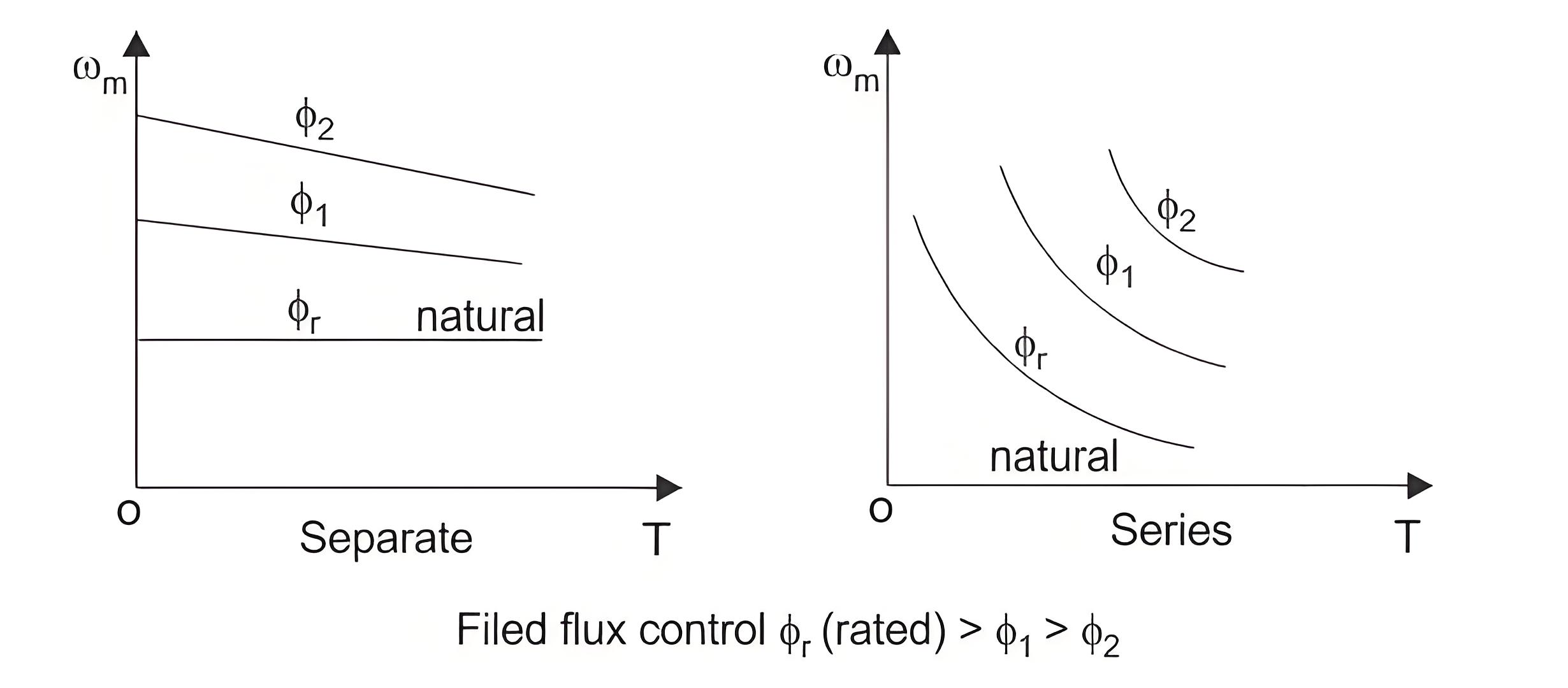
When speed control is required above the rated speed, field flux control is used. Normally in ordinary machines, the maximum speed can be allowed up to twice of the rated speed and for specially designed machines this can be allowed up to six times of the rated speed. The torque speed characteristics for field flux control are shown in the figure below.
Armature resistance control
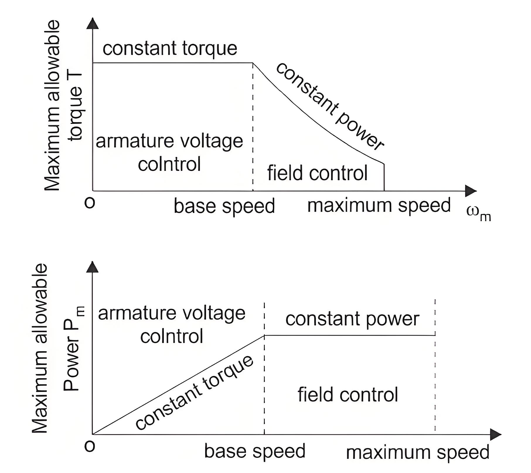
The resistance control method adjusts speed by introducing a resistor in series with the armature, which dissipates power. This inefficient method is seldom used, typically only where brief speed control is needed, like in traction systems.
The Electricity Encyclopedia is dedicated to accelerating the dissemination and application of electricity knowledge and adding impetus to the development and innovation of the electricity industry.

