How Electrical Drives are Controlled ?
How Electrical Drives are Controlled ?
Electrical Drives Definition
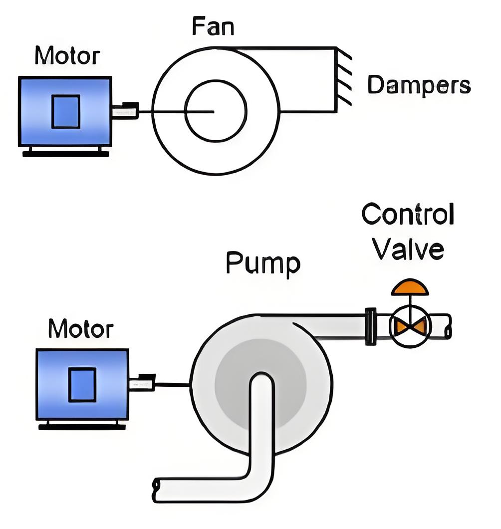
Electrical drives are systems that control the operation of electric motors, including starting, speed control, and braking.
Importance of Control
Controlling electrical drives is essential to prevent damage from sudden changes in voltage or current.
Closed Loop Control
Control systems can be open loop or closed loop control system. In an open loop control system, the output does not affect the input, making the control independent of the output. In contrast, a closed loop system uses feedback from the output to adjust the input. If the output exceeds a set value, the input is reduced, and vice-versa. closed loop control system in electrical drives helps protect the system, enhance response speed, and improve accuracy.
Protection
Enhancement of speed of response
To improve steady-state accuracy
In the following discussions, we will see through different closed loop configurations which are used in electrical drives irrespective of the type of supply they are fed, i.e DC or AC.
Current Limit Control
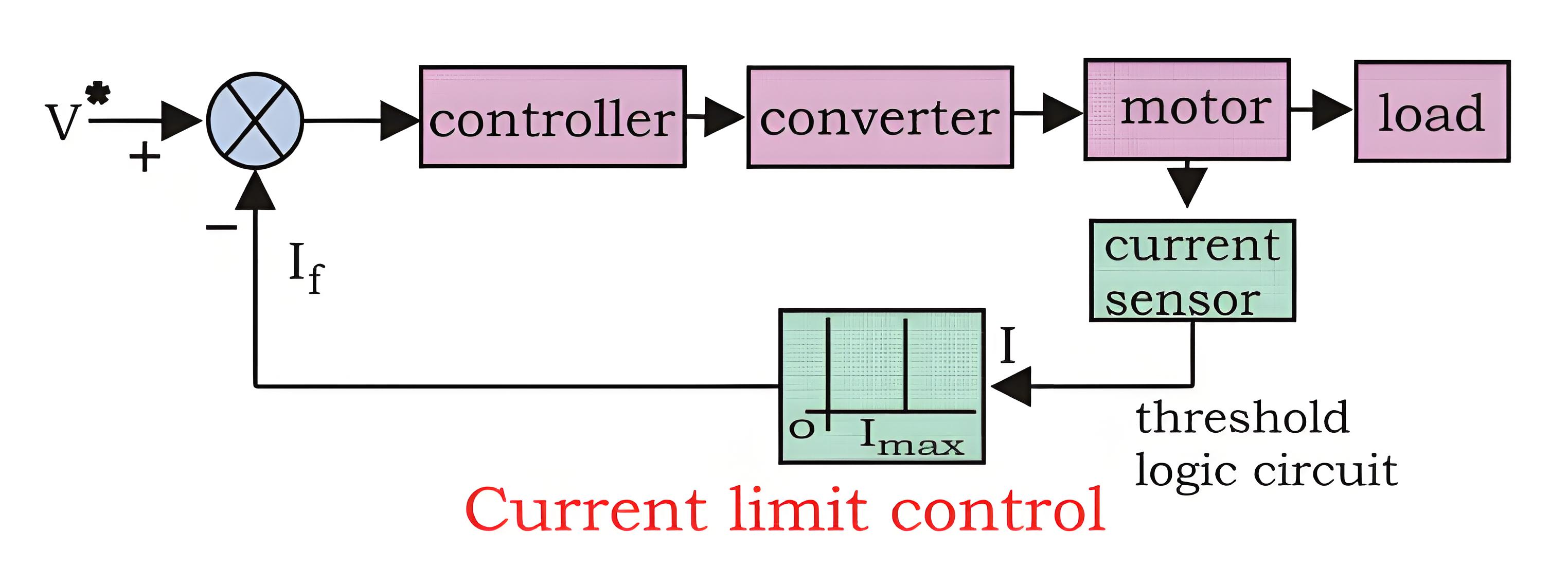
During start-up, motors can experience a huge current flow if precautions are not taken. A current limit controller is used to manage this. It monitors the current and, if it exceeds safe limits, the feedback loop activates to reduce the current. Once it’s back to a safe level, the feedback loop deactivates, ensuring normal operation.
Closed Loop Torque Control
This type of torque controller is seen mainly in battery operated vehicles like cars, trains etc. the accelerator present in the vehicles is pressed by the driver to set the reference torque T. The actual torque T follows the T which is controlled by the driver via accelerator.*

Closed Loop Speed Control
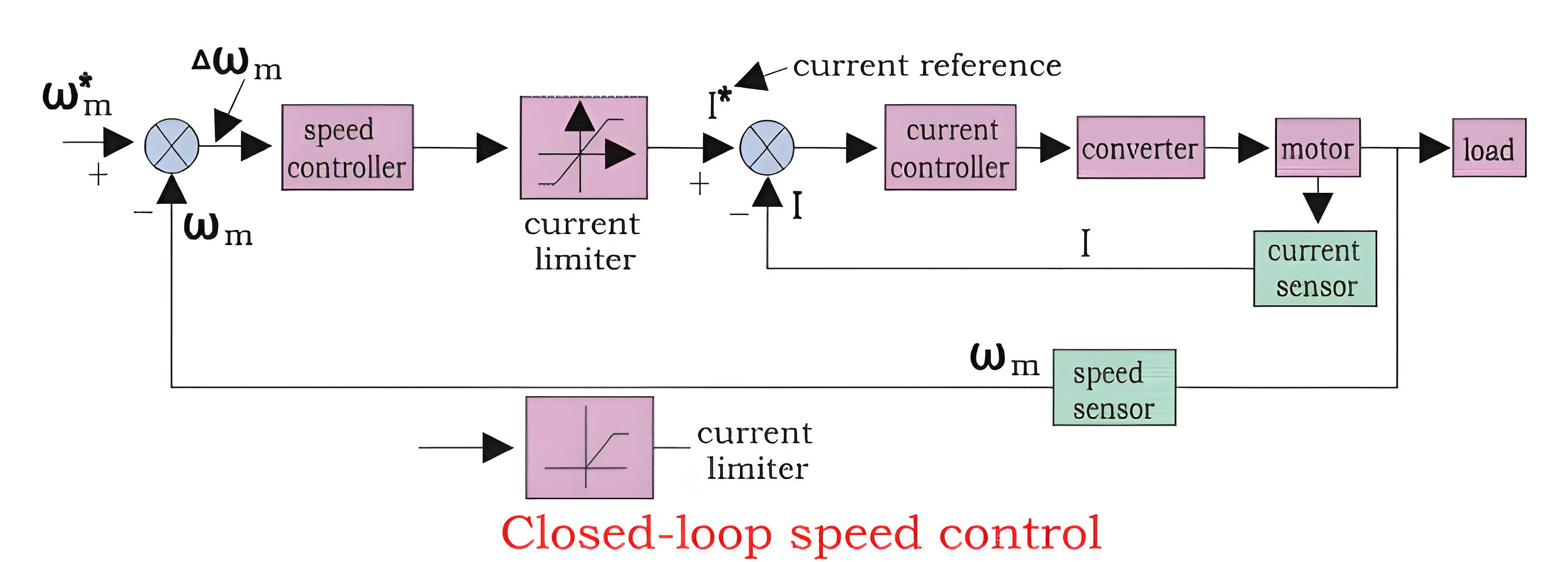
Speed control loops are widely used feedback loops in electrical drives. Looking at a block diagram can help understand how they work.
We can see from the diagram that there are two control loops, which can be said as an inner loop and outer loop. The inner current control loop limits the converter and motor current or motor torque below the safe limit. Now we can understand the function of the control loop and drive by practical examples. Suppose the reference speed W m* increases and there is a positive error ΔWm, which indicates that the speed is needed to be increased.
Now the inner loop increases the current keeping it under maximum allowable current. And then the driver accelerates, when the speed reaches the desired speed then the motor torque is equal to the load torque and there is a decrease in the reference speed Wm which indicates that there is no need of any more acceleration but there must be deceleration, and braking is done by the speed controller at maximum allowable current. So, we can say that during speed controlling the function transfers from motoring to braking and from braking to motoring continuously for the smooth operation and running of the motor.
The Electricity Encyclopedia is dedicated to accelerating the dissemination and application of electricity knowledge and adding impetus to the development and innovation of the electricity industry.
