How work operation amplifier (O- Pamp)?
How Does an Operational Amplifier Work?
An operational amplifier (Op-Amp) is a highly integrated electronic component widely used in circuits for signal amplification, filtering, integration, differentiation, and many other applications. Its primary function is to amplify the difference in voltage between its two input terminals. Here is an explanation of how an operational amplifier works and key concepts:
1. Basic Structure
An operational amplifier typically has five pins:
Non-Inverting Input (V+): Positive input terminal.
Inverting Input (V−): Negative input terminal.
Output (Vout ): Amplified output signal.
Positive Supply (Vcc ): Positive power supply voltage.
Negative Supply (Vee ): Negative power supply voltage.
2. Working Principle
Assumptions for an Ideal Operational Amplifier
Infinite Gain: Ideally, the gain A of the op-amp is infinite.
Infinite Input Impedance: The input impedance Rin is infinite, meaning the input current is almost zero.
Zero Output Impedance: The output impedance Rout is zero, meaning the output current can be arbitrarily large without affecting the output voltage.
Infinite Bandwidth: Ideally, the op-amp can operate at all frequencies without any limitations.
Characteristics of a Real Operational Amplifier
Finite Gain: In practice, the gain A of the op-amp is finite, typically ranging from Ten to the fifth power to Ten to the sixth power.
Finite Input Impedance: The actual input impedance is not infinite but is very high (megohms level).
Non-Zero Output Impedance: The actual output impedance is not zero but is very low.
Finite Bandwidth: The actual bandwidth of the op-amp is limited, typically ranging from hundreds of kilohertz to megahertz.
3. Basic Operating Modes
Open-Loop Configuration
Open-Loop Gain: In open-loop configuration, the op-amp's gain A directly amplifies the differential input voltage

Saturation: Due to the high gain A, even a small input voltage difference can cause the output voltage to reach the limits of the power supply voltages (i.e., Vcc or Vee ).
Closed-Loop Configuration
Negative Feedback: By introducing negative feedback, the gain of the op-amp can be controlled to operate within a reasonable range.
Negative Feedback Circuit: Common negative feedback circuits include inverting amplifiers, non-inverting amplifiers, and differential amplifiers.
Virtual Short and Virtual Open: In negative feedback circuits, the voltages at the two input terminals of the op-amp are almost equal (virtual short), and the input current is almost zero (virtual open).
4. Common Application Circuits
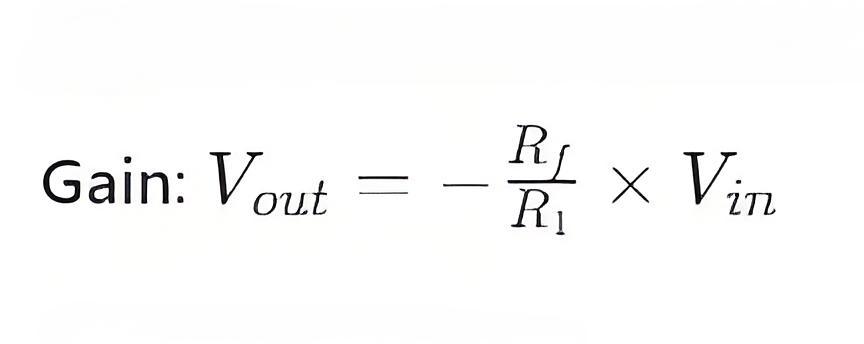
Inverting Amplifier
Circuit Structure: The input signal is fed through a resistor
Circuit Structure: The input signal is fed through a resistor R1 to the inverting input V − , and a feedback resistor Rf connects the output
Vout to the inverting input V- .
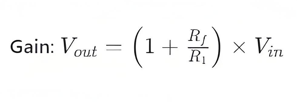
Non-Inverting Amplifier
Circuit Structure: The input signal is fed through a resistor R1 to the non-inverting input V + , and a feedback resistor Rf connects the output Vout to the inverting input V− .
Differential Amplifier
Circuit Structure: Two input signals are applied to the non-inverting input V+ and the inverting input V− , and a feedback resistor Rf connects the output V out to the inverting input V − .

5. Summary
An operational amplifier works by amplifying the difference in voltage between its two input terminals, with the core functionality relying on high gain and negative feedback mechanisms. By using different circuit configurations, op-amps can perform various functions such as amplification, filtering, integration, and differentiation. Understanding the working principles and common application circuits of op-amps is essential for designing and troubleshooting various electronic systems.
The Electricity Encyclopedia is dedicated to accelerating the dissemination and application of electricity knowledge and adding impetus to the development and innovation of the electricity industry.
