What is the meaning of 5P20 in a current transformer?

Encyclopedia
10/24/2024

Analysis of the Meaning of 5P20 in Current Transformers

Explanation of Accuracy Grade

In current transformers (CTs), 5P20 is an identifier that represents its performance characteristics. This identifier consists of three parts: Accuracy Class, Protection Class, and Accuracy Limit Factor.

  • Accuracy Class (5): The number 5 represents the accuracy class of this current transformer. The accuracy class reflects the measurement error of the current transformer under specific conditions. A smaller number indicates higher accuracy. Accuracy class 5 is typically used for applications that do not require high precision, such as monitoring or protection, where small errors in measurement are acceptable.

  • Protection Grade (P): The letter P denotes that this is a current transformer for protection purposes. Protection grade current transformers are designed to carry fault currents and maintain their accuracy under fault conditions.

  • Accuracy Limit Factor (20): The number 20 represents the Accuracy Limit Factor (ALF) of the current transformer. This factor indicates the magnitude of the fault current that can safely flow through the primary winding of the CT without causing it to saturate. In this case, it means that when the primary current reaches 20 times the rated current due to a short circuit, the composite error of the transformer is less than 5%.

Practical Application

Current transformers of the 5P20 type are typically used in applications that can accept lower levels of accuracy, such as some general-purpose monitoring or control systems. While they may not be suitable for applications requiring high precision current measurements, in many cases, they offer sufficient performance and remain a popular choice due to their cost-effectiveness and reliability.

Summary

In summary, 5P20 denotes a protective class current transformer with an accuracy class of 5, capable of maintaining a total error within 5% when the primary current is up to 20 times its rated current. This characteristic makes it widely applicable in various protection and monitoring applications.

Encyclopedia

The Electricity Encyclopedia is dedicated to accelerating the dissemination and application of electricity knowledge and adding impetus to the development and innovation of the electricity industry.
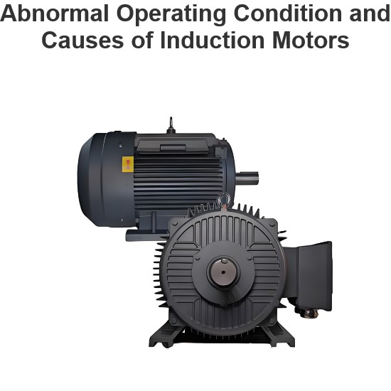
Abnormal Operating Condition and Causes of Induction Motors
Abnormal Operating Conditions and Causes of Induction MotorsThree-phase induction motors are widely used in industrial applications. Their abnormal operating conditions and causes can be summarized as follows:Abnormal Operating Conditions and Causes of Induction MotorsThe following are the abnormal operating conditions and causes of induction motors:Mechanical OverloadBlockage in Pump/Gear Systems: Obstruction in mechanical systems (e.g., pumps or gears) connected to the motor.Damaged Bearings o
Edwiin
05/19/2025
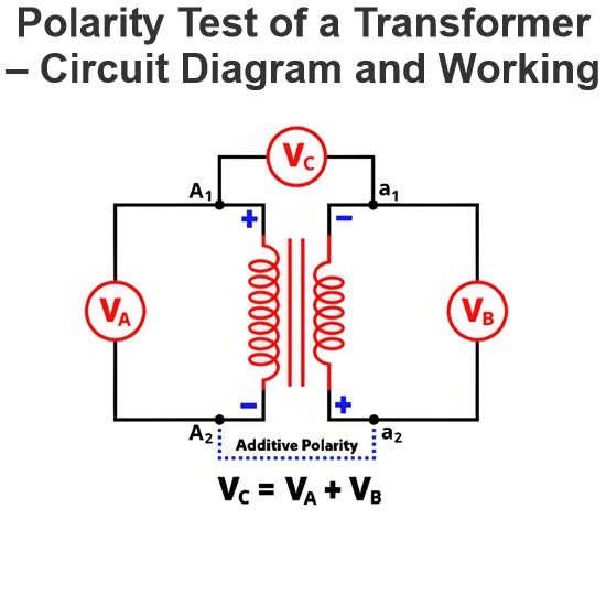
Polarity Test of a Transformer – Circuit Diagram and Working
Polarity in Two-Winding TransformersIn two-winding transformers, one terminal of a winding is always positive relative to the other at any instant. Transformer polarity refers to therelative direction of induced voltagesbetween the high-voltage (HV) and low-voltage (LV) windings. In practical transformers, winding terminals are brought out as leads, and polarity defines how these leads are connected and labeled.Significance of Transformer PolarityUnderstanding polarity is critical for several op
Edwiin
05/15/2025
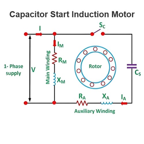
Capacitor Start Induction Motor
Capacitor Start Motors are a type of single - phase induction motors. They utilize a capacitor within the auxiliary winding circuit to create a significant phase difference between the current flowing through the main winding and that in the auxiliary winding. As the name "capacitor start" clearly implies, these motors rely on a capacitor specifically for the starting process. The diagram below illustrates the connection schematic of a Capacitor Start Motor.The capacitor start motor features a c
Encyclopedia
05/09/2025
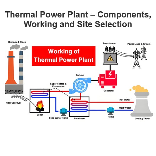
 Thermal Power Plant – Components, Working and Site Selection
Thermal Power Plant – Components, Working and Site Selection
What is a Thermal Power Plant?The law of energy conservation states that energy cannot be created or destroyed; rather, it can only be transformed from one form to another. Electrical energy, in particular, can be harnessed from a variety of energy sources. Facilities designed to generate large - scale electrical energy are commonly referred to as power plants or power stations.A thermal power plant is a type of power generation facility that converts heat energy into electrical energy. Heat ene
Encyclopedia
05/07/2025
Inquiry
Download
Experts Electrical is dedicated to serving the personnel in the global power industry.
Join Experts Electrical, not only can you discover power equipment and power knowledge, but also canhnd like - minded friends!