Wave Winding: Simplex, Duplex, Retrogressive And Progressive Wave Windings
Wave Winding: Simplex, Duplex, Retrogressive And Progressive Wave Windings
Key learnings:
Wave Winding Definition: A wave winding is defined as a type of armature winding where the end of one coil connects to the start of another, creating a wave-like pattern.
Simplex Wave Winding: Simplex wave winding has odd back pitch and front pitch that are nearly equal and suitable for high voltage, low current machines.
Duplex Wave Winding: Duplex wave winding involves two parallel paths and is used for higher current ratings.
Retrogressive Wave Winding: In retrogressive wave winding, after one round of the armature, the coil falls into a slot left of its starting slot.
Progressive Wave Winding: In progressive wave winding, after one round of the armature, the coil falls into a slot right of its starting slot.
What is a Wave Winding?
A wave winding (also known as a series winding) is defined as a type of armature winding in DC machines, alongside lap winding.
In a wave winding, we connect the end of one coil to the start of another coil of the same polarity. The coil side (A – B) progresses forward around the armature to another coil side and goes on successively passing through North and South poles until it returns to a conductor (A1-B1) lying under the starting pole.
This winding forms a wave with its coil, that’s why we call it a wave winding. Since we connect the coils in series, it is also referred to as a series winding. A diagram of a wave winding configuration is shown below.
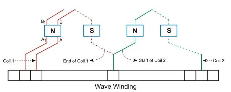
Wave windings can be further classified into:
Simplex wave windings
Duplex wave windings
Retrogressive wave windings
Progressive wave windings
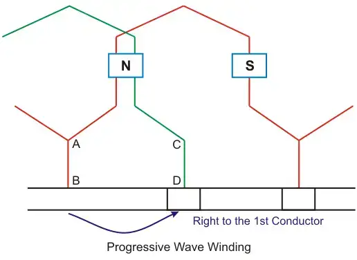
Progressive Wave Winding
If, after one round of the armature, the coil falls into a slot to the right of its starting slot, it is called progressive wave winding.
Retrogressive Wave Winding
If, after one round of the armature, the coil falls into a slot to the left of its starting slot, it is called retrogressive wave winding.
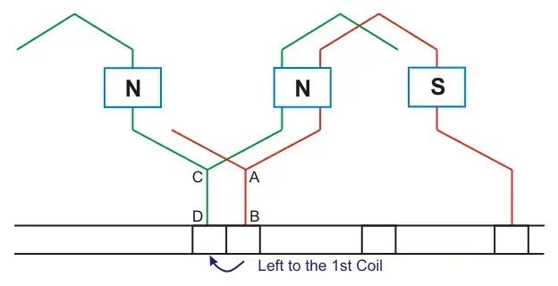
Here in the picture above we can see that 2nd conductor CD is in the left of the 1st conductor.
Important Points about Simplex Wave Winding
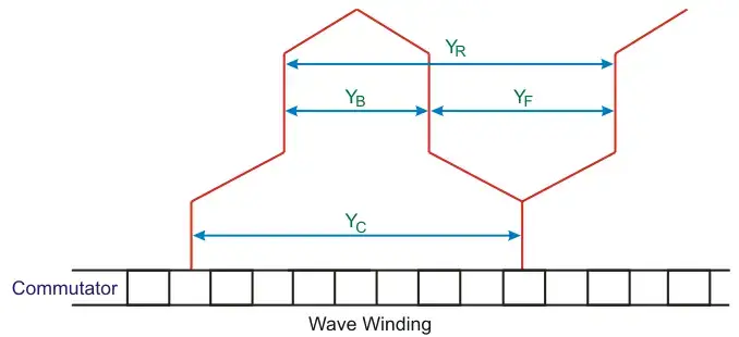
In simplex wave winding, the back pitch (YB) and front pitch (YF) are both odd and have the same sign.
The back-pitch and front-pitch are nearly equal to the pole pitch and maybe equal or differ by ±2. + for progressive winding, – for retrogressive winding.

Here, Z is the no of conductors in the winding. P is the no of poles.
Average pitch (YA) must be an integer number, because it may close itself.
We take ± 2 (two) because after one round of the armature the winding falls sort of two conductors.
If we take an average pitch Z/P then after one round the winding will close itself without including all coil sides.
Since average pitch must be an integer, this winding is not possible with any no. of conductors.
Let us take 8 conductors in a 4 pole machine.

Being fractional no the wave winding is no possible but if there was 6 conductors then the winding can be done. Since,

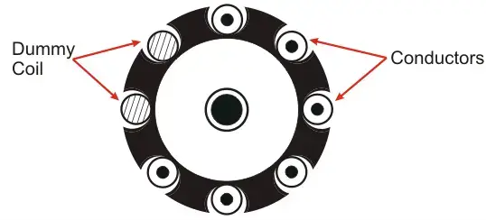
For this problem the DUMMY COILS are introduced.
Dummy Coil
Wave winding is only possible with specific numbers of conductors and slot combinations. Standard stampings in the winding shop might not always match the design requirements, so dummy coils are used in such cases.
These dummy coils are placed in the slots to give the machine the mechanical balance but they are not electrically connected to the rest of the winding.
In multiplex wave winding:

Where:
m is the multiplicity of the winding
m = 1 for simplex winding
m = 2 for duplex winding

Construction of Wave Windings
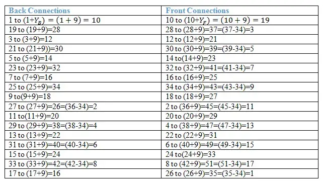
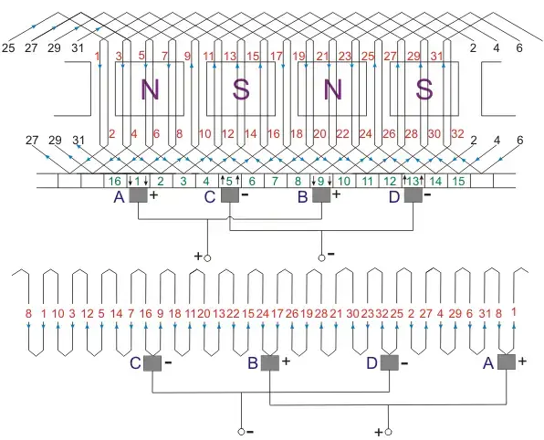
Let us develop a simplex and progressive wave winding diagram of a machine having 34 conductors in 17 slots and 4 poles.
Average pitch:

Now we have to construct a table for the connection diagram:
Wave Winding Diagram
Simplex Wave Winding Advantages
The advantages of simplex wave windings include:
In this winding, only two brushes are required but more parallel brushes can be added to make it equal to the no. of poles. If one or more brushes set poor contacts with the commutator, satisfactory operation is still possible.
This winding gives sparkles commutation. The reason behind that it has two parallel paths irrespective of the number of poles of the machine. The conductors in each of the two parallel paths distributed around the armature in the entire circumference.
No. of conductors in each path = Z/2, Z is the total no. of conductors.
Generated emf = average emf induced in each path X Z/2
For a given number of poles and armature conductors, it gives more emf than that of lap winding. Hence wave winding is used in high voltage and low current machines. This winding is suitable for small generators circuit with a voltage rating of 500-600V.
Current flowing through each conductor.

Ia is the armature current. The current per path for this kind of winding must not be exceeded 250A.
The resultant emf around the entire circuit is zero.
Simplex Wave Winding Disdvantages
The disadvantages of simplex wave windings include:
Wave winding cannot be used in machines having higher current rating because it has only two parallel paths.
The Electricity Encyclopedia is dedicated to accelerating the dissemination and application of electricity knowledge and adding impetus to the development and innovation of the electricity industry.
