Rogowski Coil: What is it & How Does it Work?
What is a Rogowski Coil?
The Rogowski coil is defined as an electrical device that is used to measure alternating current (AC). It is also used to measure the high-speed transient, pulsed current or sinusoidal current. The name Rogowski coil was named after the German physicist Walter Rogowski.
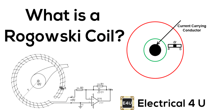
A Rogowski coil is an evenly wounded coil with N number of turn and constant cross-section area A. There is no metal core in a Rogowski coil.
The end terminal of the coil is returned through the central axis of the coil to another end. Therefore, both terminals are at the same end of the coil.
This entire assembly wrapped around the current-carrying conductor whose current we need to measure.
How does a Rogowski Coil Work?
Rogowski coils work on the principle of faraday’s law. It is similar to AC current transformers (CTs). In current transformers, the voltage induced in a secondary coil is proportional to the current flow through the conductor.
The difference between Rogowski coils and AC current transformers is in the core. In Rogowski coils, an air core is used and in the current transformer, a steel core is used.
When current passes through the conductor, it will create a magnetic field. Due to an intersection with a magnetic field, a voltage is induced between the terminals of the Rogowski coil.
The magnitude of voltage is proportional to the current passes through the conductor. Rogowski coils are close pathed. Generally, the output of Rogowski coils is connected with the integrator circuit. So, the coil voltage is then integrated to provide an output voltage that is proportional to the input current signal.
Rogowski Coil Current Sensor
Rogowski coil current sensors are preferred due to no magnetic saturation, no overheating, or no hysteresis loss. As such there are very low magnetic losses in Rogowski coils. And it has very low insertion impedance.
It is able to sense the current flowing through the conductor. Hence Rogowski coils can also function as current sensors.
Rogowski coils are an air-cored toroidal winding wrapped on a conductor. For large currents, the output does not saturate due to the non-magnetic core.
It can be designed for a wide range of current measurements as well as protection applications. Rogowski coil sensor converts the input current to an output voltage. And it can sense the current flowing the conductor by integrating the output voltage.
There are two types of Rogowski coils; Rigid and Flexible.
Rogowski Coil Design
Consider the conductive element ‘dr’ at distance ‘x’ from the origin. The current-carrying conductor is placed at the center of the coil. The figure below shows the arrangement of a typical Rogowski coil.
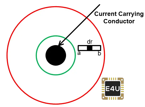
Rogowski Coil
As per biot-savart law, the magnetic strength at distance x is given by;
The magnetic flux density at point ‘dr’ is
(2) ![]()
Where μ is the permeability of free space
From the above equations, the magnetic flux density due to a current flowing through the conductor is
The magnetic flux is given as
Where dA is rectangular cross-section area for element ‘dr’ and that is given as
Therefore, total flux is
As per Lenz’s law, the voltage induced due to N turns is
So, mutual inductance (M) for the Rogowski coil is
Now, assume that sinusoidal current flowing through the conductor with an amplitude ‘Im’ and frequency ‘f’.
So, the voltage induced in the Rogowski coil is given by
At time t=0, the magnitude of voltage is maximum. So, the peak voltage is given as;
RMS value of the voltage;
Hence, the induced voltage is proportional to RMS current flowing through the conductor and frequency of the current.
Rogowski Coil Integrator
An ideal hardware integrator would introduce 90˚ phase shift. When designing hardware, there are practical limitations. That results in phase error compared to the ideal result 90˚. By choosing careful component this error may be reduced.
According to components used in integrator, there are two types of integrator;
Passive Integrator
Active Integrator
Passive Integrator
For a large output range of Rogowski coils, the series RC circuit act as an integrator. The value of the acceptable phase error decides the value of Resistance (R) and Capacitance (C).
The relationship between R and C and phase error can be derived from the phasor diagram of the RC network. And it is as shown in the below figure.

Passive Integrator
In the phasor diagram,
VR and VC represent the voltage drop across the resistor and capacitor,
IT is the net current in the network,
V0 is the output voltage. This voltage is the same as the voltage across the capacitor (VC),
VIN is the input voltage. It is a vector sum of a voltage drop across the resistor and capacitor.
The voltage drop across the resistor is in-phase and a voltage drop across the capacitor will lag by 90˚ with respect to the net current.
The phase angle between VIN and V0 is known as the phase difference between the integrator’s input and output and this angle should be close to 90˚.
The deviation between the actual phase angle and ideal phase angle is phase error and it is represented by ф.
If we increase the drop across the resistor (VR’), the phase will decrease.
The value of R and C can be estimated by the below equations.
Where,
Ф = Target phase error
XC = Capacitive Impedance
R = Resistance
f = Input Frequency
In this equation, assume the value of R or C and find the value of the remaining element.
Active Integrator
The RC circuit act as an attenuator and drop across the capacitor gets attenuated. At a low current level, when the output voltage is very low and it is in terms of microvolt (μV). It creates a poor signal at the input of Analog to Digital Converter (ADC). This problem occurs in the RC circuit for low current.
This problem can be solved by using an Active Integrator. The circuit of an active integrator is as shown in the below figure.
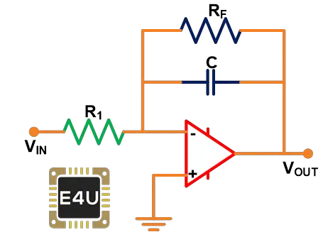
Active Integrator
Here, the RC element is in a feedback path of an Amplifier. The gain of the amplifier can be adjusted by using the below equation.
The advantages of Rogowski coils include:
It can respond to fast-changing currents.
The second terminal of the coil is returning to the first terminal. And it makes an open circuit coil. So, there is no danger of opening of the secondary coil.
The air is used as a medium. There is no magnetic core is used. So, there is no question of saturation of the core.
In this coil, temperature compensation is simple.
In order to keep output current constant, the AC current transformer (CT) needs to increase the number of secondary turns for large currents. Hence, for equal rating, the size of the Rogowski coil is small compared to a conventional current transformer.
It is available in two types; flexible as well as rigid.
Disadvantages of Rogowski Coil
The disadvantages of Rogowski coils include:
To obtain the current waveform, the output of the coil must be pass through the integrator circuit. It needs a power supply of 3V to 24Vdc.
It cannot measure the DC current.
Statement: Respect the original, good articles worth sharing, if there is infringement please contact delete.
Electrical4U is dedicated to the teaching and sharing of all things related to electrical and electronics engineering.

