Synchronous Motor Excitation
Synchronous Motor Excitation
Prior to understanding this synchronous motor excitation, it should be remembered that any electromagnetic device must draw a magnetizing current from the AC source to produce the required working flux. This magnetizing current lags by almost 90o to the supply voltage. In other words, the function of this magnetizing current or lagging VA drawn by the electromagnetic device is to set up the flux in the magnetic circuit of the device.The synchronous motor is doubly fed electrical motor Synchronous converts electrical energy to mechanical energy via magnetic circuit. Hence, it comes under electromagnetic device. It receives 3 phase AC electrical supply to its armature winding and DC supply is provided to rotor winding.
Synchronous motor excitation is defined as the DC supply given to the rotor to produce the necessary magnetic flux.
A unique characteristic of synchronous motors is that they can operate at any power factor—leading, lagging, or unity—depending on excitation. At a constant applied voltage (V), the required air gap flux stays constant. This flux is created by both the AC supply to the armature winding and the DC supply to the rotor winding.
CASE 1: When the field current is sufficient enough to produce the air gap flux, as demanded by the constant supply voltage V, then the magnetizing current or lagging reactive VA required from ac source is zero and the motor operate at unity power factor. The field current, which causes this unity power factor is called normal excitation or normal field current.
CASE 2: If the field current is insufficient to produce the required air gap flux, additional magnetizing current is drawn from the AC source. This extra current creates the missing flux. In this case, the motor operates at a lagging power factor and is said to be under-excited.
CASE 3: If the field current exceeds the normal level, the motor is over-excited. This excess field current generates extra flux, which must be balanced by the armature winding.
Hence the armature winding draws leading reactive VA or demagnetizing current leading voltage by almost 90o from the AC source. Hence in this case the motor operate under leading power factor.
This whole concept of excitation and power factor of synchronous motor can be summed up in the following graph. This is called V curve of synchronous motor.
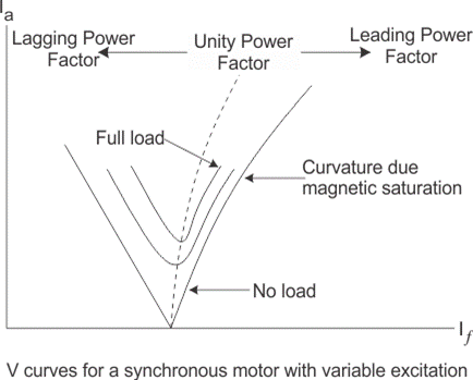
Conclusion: An overexcited synchronous motor operate at leading power factor, under-excited synchronous motor operate at lagging power factor and normal excited synchronous motor operate at unity power factor.
The Electricity Encyclopedia is dedicated to accelerating the dissemination and application of electricity knowledge and adding impetus to the development and innovation of the electricity industry.
