Centrifugal Switches: What Are They And How Do They Work
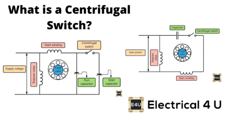
What is a Centrifugal Switch?
A centrifugal switch is an electrical switch powered by the centrifugal force created by a rotating shaft. This centrifugal force is typically provided by a gasoline engine or electric motor. Centrifugal switches are designed to activate or deactivate the rotational speed of the shaft.
How do Centrifugal Switches work?
A centrifugal switch is an electrical switch normally found in signal phase induction motors and split-phase induction motors.
This switch is used to provide a controlled switching operation that is required in the engine when the specified engine speed is generated.
The centrifugal switch is based on the concept of centrifugal force. It’s just an electric switch. These switches are specially designed for induction motors in single and split phases.
As its operation is identical to that of a centrifugal clutch used in vehicles, the centrifugal switch is generally known as a ‘clutch’.
A single-phase AC engine has a centrifugal switch inside its case, which is attached to the engine shaft. When the engine is off and motionless, the switch is closed.
When the engine is switched on, the switch drives electricity to the capacitor and the extra coil winding in the engine, increasing its starting torque. As the engine’s revolutions increase per minute, the switch opens, as the engine no longer needs a boost.
A centrifugal switch solves a problem associated with single-phase AC electric motors. They do not develop enough torque on their own to start turning from a dead stop.
A circuit switches on the centrifugal switch, providing the requisite boost to start the motor. The switch turns off the boost circuit until the motor reaches its running speed, and the motor runs normally.
Centrifugal Switch Symbol
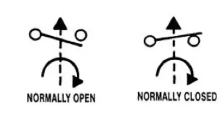
A centrifugal switch is a type of switch and it can be represented by an electronic symbol. An electronic symbol is a pictogram used in the schematic diagram of an electrical or electronic circuit to represent various electrical and electronic devices or functions, such as wires, batteries, resistors and transistors.
Centrifugal Switch Symbol
A switch is an electrical feature in electrical engineering that can disconnect or connect the conducting route in an electrical circuit, disrupt or redirect the electrical current from one conductor to another.
Centrifugal switch is a switch that is operated by shaft rotation. It is responsive to speed or direction by opening only on the increasing speed.
How to Test a Centrifugal Switch?
Always it is better to test the centrifugal switch before using it for applications. The following criteria should be met by an ideal centrifugal switch:
Throughout its life cycle, the process should be uniform.
For simplicity of design and low production cost, the number of components of the equipment should be minimal.
It should have marginal elements of friction.
Without causing any significant design changes, the cut-out/cut-in ratio should be readily modifiable.
The switch is readily accessible as the communication unit of the switch is present on the outside of the motor frame. So, without dismantling the motor assembly, the switch can be tested, washed, and replaced.
What happens if the centrifugal switch does not open?
If the start switch does not open when it is needed, the start winding will overheat and flame out, and the engine will not start next time. If the centrifugal start switch is not closed, the engine will overheat the main winding without any main winding failure.
What is the effect if the centrifugal switch is not disconnected after the motor starts?
The centrifugal switch should be disconnected at about 70 to 80 per cent of the full speed of the engine. If it is not disconnected, a heavy current will continue to flow through the starting winding of the engine, which eventually results in the failure of the starting winding and engine. Also, the speed and the current cannot reach its maximum.
What is the purpose of a centrifugal switch in the end of an open motor?
A centrifugal switch is an electrical switch that operates using the centrifugal force generated by a rotating shaft, most commonly an electric motor or a gasoline engine. Here, the switch is used to disconnect the starting winding of the engine as soon as the engine is approaching its normal operating speed.
Do all single phase motors have a centrifugal switch?
There is no centrifugal switch so that the start winding becomes an auxiliary winding when the engine reaches running speed, making it essentially a two-phase motor. They are considered to be the most reliable single-phase motors because there is no centrifugal starting switch.
Centrifugal Switch in Induction Motors
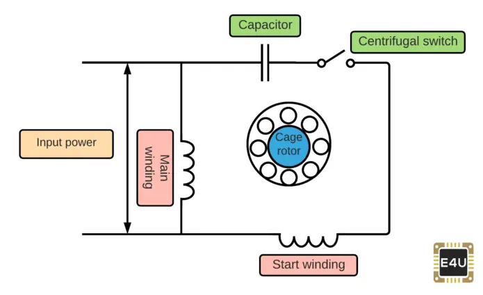
To understand how this switch works in induction motors, let us first understand the model of induction motors. Induction engines consist of the single stator winding and auxiliary winding. A single-phase AC current is applied to the winding of the stator.
But the single stator winding cannot produce enough of the rotating field needed to generate the starting torque. As a result, an auxiliary winding is provided.
This auxiliary winding generates a field that is out of phase with the field generated by the winding of the stator. The resulting field, therefore, produces a starting torque and starts the engine. Once the engine is started, the rotor sets up a pulsating field that does not include the stator filed.
When the engine speed reaches a specified percentage of the synchronous speed, the circuit that energizes the auxiliary winding must be disconnected.
This is where the centrifugal switch comes into the picture for the induction engines. Here the centrifugal switch helps the circuit to be opened and the auxiliary winding disconnected.
Centrifugal Switch in Induction Motor
Why is the Centrifugal Switch Used in Most Single-Phase Induction Motors?
In all common induction motor which is used in drill presses, furnaces, table saws, pumps, grinders, washers and dryers, the centrifugal switches are used together with an additional winding to start the motor.
Single-phase induction motors require the start of auxiliary circuits. In very small engines like cooling fans, they can be on the circuit at all times.
But it wastes electricity, and it generates heat. This is tolerable in a small engine, but above 1/10hp or so it becomes attractive to turn off the starting circuit after the engine is spinning. A centrifugal switch is used to do this.
The common induction motor for the single-phase cannot begin on its own, it only sits still and noisy for about 30 seconds and then burns the isolation off the coils. So we have to start, and that’s where the centrifugal switch and the extra winding come in.
The engine starts happily on its own with an extra winding. However, this must be turned off before maximum speed is reached; otherwise, the initial winding would burn off, as the subsidiary winding is only planned for a few seconds.
Three factors can be seen during engine operation. The force of the spring decreases linearly. At the rate proportional to the rotor speed the centrifugal force increases. The weight radius will be increased.
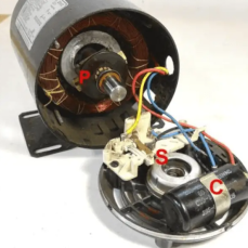
In the figure below, you can see “P” on the rotor shaft of the centrifugal devices that force the “S” electrical switch to switch off the engine’s start winding. A capacitor is inserted to change the process a little extra to get more starting torque.
Centrifugal Switch in Single-Phase Induction Motors
What Type of Split Phase Motor Does Not Generally Contain a Centrifugal Switch?
Generally, the capacitor-start capacitor-run split-phase motor does not contain a centrifugal switch to disconnect the starting winding.
There is a cage rotor for the Capacitor Start Capacitor Run Motor, and its stator has two windings, known as main and auxiliary windings. In space, the two windings are shifted 90 degrees.
In this system, there are two capacitors, one of which is used at the time of start and is known as the starting capacitor. The other one is used to operate the motor continuously and is known as a working condenser.
So this engine is called Capacitor Start Motor Run Capacitor Run. This motor is also known as the Two Value Capacitor Motor. In the below-shown figure, there are two capacitors in this motor represented as start capacitor and run capacitor.
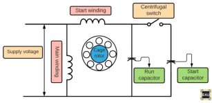
Centrifugal Switch in Split Phase Motor
A Permanent Split Capacitor (PSC) Motor another type of single-phase AC motor more specifically, a type of split-phase induction motor in which the capacitor is permanently connected. It does not require a centrifugal switch.
It also has a cage rotor, similar to that of a Capacitor Start and Capacitor Start Capacitor Run Motor, and the two windings called as main and auxiliary windings. It has only one capacitor with the starting winding connected in series.
At both the starting and running conditions, the capacitor C is permanently attached to the circuit. It is also called the Capacitor Motor Single Value. Since the capacitor is still in the circuit, no starting switch is given for this type of motor.
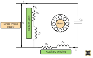
Permanent Split Capacitor Motor
Applications of a Centrifugal Switch
This switch is often used in systems where speed detection in systems is necessary for the computer to be safe and operate properly.
The following are some of the uses of the centrifugal switch:
Defense against Overspeed in motors, generators, etc.
Used in DC motors, conveyors, escalators, lifts, etc.
These are also used in devices such as blowers, fans as well as conveyors to detect under-speed.
Material losses are often used in systems where the loss of speed could lead to damage of the device.
Statement: Respect the original, good articles worth sharing, if there is infringement please contact delete.
Electrical4U is dedicated to the teaching and sharing of all things related to electrical and electronics engineering.

