Permanent Split Capacitor (PSC) Motor

Edwiin
05/10/2025

The Permanent Split Capacitor (PSC) motor also features a cage rotor, and it has two windings, namely the main winding and the auxiliary winding, which are similar to those in a Capacitor Start motor and a Capacitor Start Capacitor Run motor. However, in a PSC motor, there is only one capacitor that is connected in series with the starting winding. This capacitor remains permanently connected within the circuit, functioning both during the starting process and when the motor is running.

The connection diagram of a Permanent Split Capacitor motor is illustrated as follows:

image.png

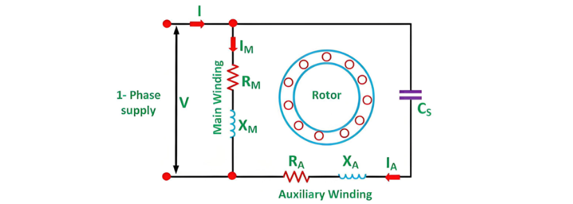
It is also known as a Single Value Capacitor motor. Since the capacitor remains constantly in the circuit, this type of motor does not incorporate any starting switch. The auxiliary winding is always present in the circuit. As a result, the motor functions as a balanced two-phase motor, generating a uniform torque and operating without noise.

Advantages of Permanent Split Capacitor (PSC) Motor

The Single Value Capacitor motor offers the following benefits:

  • There is no requirement for a centrifugal switch.
  • It has a high efficiency.
  • With the capacitor permanently connected in the circuit, it exhibits a high power factor.
  • It possesses a relatively high pullout torque.

Limitations of Permanent Split Capacitor (PSC) Motor

The limitations of this motor are as follows:

In this motor, a paper capacitor is utilized because an electrolytic capacitor cannot be used for continuous operation. The cost of the paper capacitor is higher, and its size is larger compared to an electrolytic capacitor of the same rating.

It has a low starting torque, which is less than the full load torque.

Applications of Permanent Split Capacitor (PSC) Motor

The Permanent Split Capacitor motor has diverse applications, as listed below:

  • It is used in fans and blowers of heaters and air conditioners.
  • It is employed in the compressors of refrigerators.
  • It is applied in office machinery.

This concludes the introduction to the Permanent Split Capacitor (PSC) motor.

Edwiin

Generator Protection – Types of Faults & Protection Devices
Common Generator Faults and Protection SystemsClassification of Generator FaultsGenerator faults are primarily categorized into internal and external types:Internal Faults: Arise from issues within generator components.External Faults: Stem from abnormal operating conditions or external network issues.Faults in prime movers (e.g., diesel engines, turbines) are mechanical in nature and defined during equipment design, though they must integrate with generator protections for tripping purposes.Typ
Edwiin
06/05/2025
Short Circuit Ratio of a Synchronous Machine
The Short Circuit Ratio (SCR) of a Synchronous MachineThe Short Circuit Ratio (SCR) of a synchronous machine is defined as the ratio of the field current needed to generate rated voltage under open-circuit conditions to the field current required to sustain rated armature current during a short-circuit condition. For a three-phase synchronous machine, the SCR can be derived from its Open-Circuit Characteristic (O.C.C) at rated speed and Short-Circuit Characteristic (S.C.C), as illustrated in the
Edwiin
06/04/2025
Equivalent Circuit of a Transformer
The equivalent circuit diagram of any device can be extremely useful for predicting how the device will behave under different operating conditions. It is essentially a circuit - based depiction of the equations that describe the device's performance.The simplified equivalent circuit of a transformer is constructed by representing all of the transformer's parameters on either the secondary side or the primary side. The equivalent circuit diagram of the transformer is presented below:Let the equi
Edwiin
06/03/2025
Transformer On Load Condition
Transformer Operation Under Load ConditionsWhen a transformer is under load, its secondary winding connects to a load, which can be resistive, inductive, or capacitive. A current I2 flows through the secondary winding, with its magnitude determined by the terminal voltageV2and load impedance. The phase angle between the secondary current and voltage depends on the load characteristics.Explanation of Transformer Load OperationThe operational behavior of a transformer under load is detailed as fol
Edwiin
06/03/2025
Inquiry
Download
Experts Electrical is dedicated to serving the personnel in the global power industry.
Join Experts Electrical, not only can you discover power equipment and power knowledge, but also canhnd like - minded friends!