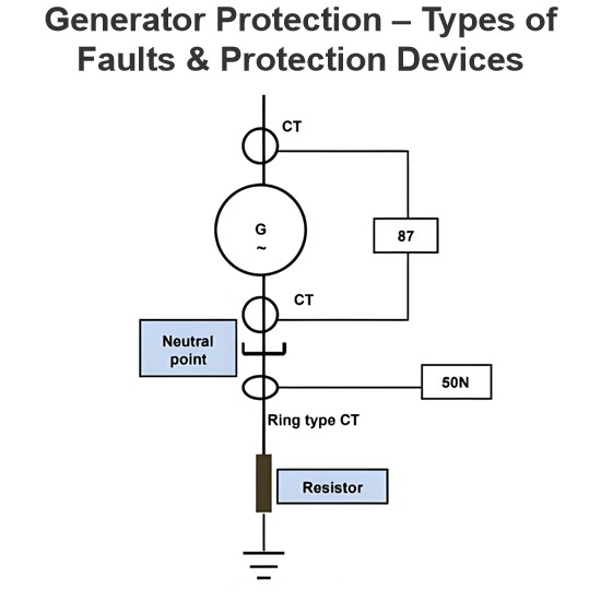
Generator Protection – Types of Faults & Protection Devices
Common Generator Faults and Protection SystemsClassification of Generator FaultsGenerator faults are primarily categorized into internal and external types:Internal Faults: Arise from issues within generator components.External Faults: Stem from abnormal operating conditions or external network issues.Faults in prime movers (e.g., diesel engines, turbines) are mechanical in nature and defined during equipment design, though they must integrate with generator protections for tripping purposes.Typ
Edwiin
06/05/2025
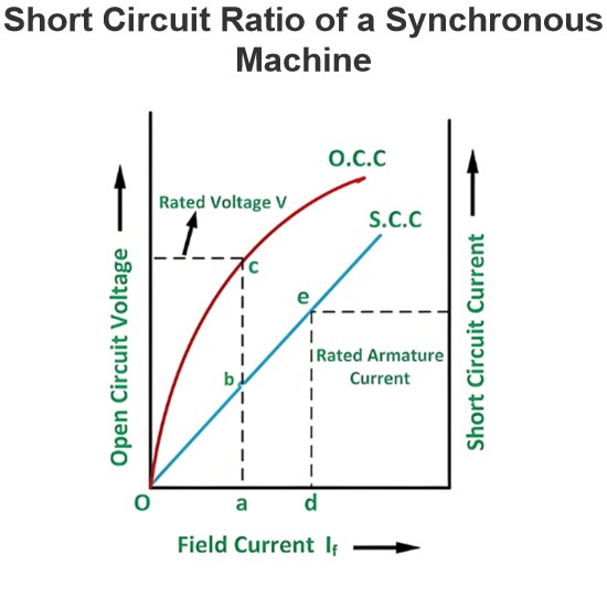
Short Circuit Ratio of a Synchronous Machine
The Short Circuit Ratio (SCR) of a Synchronous MachineThe Short Circuit Ratio (SCR) of a synchronous machine is defined as the ratio of the field current needed to generate rated voltage under open-circuit conditions to the field current required to sustain rated armature current during a short-circuit condition. For a three-phase synchronous machine, the SCR can be derived from its Open-Circuit Characteristic (O.C.C) at rated speed and Short-Circuit Characteristic (S.C.C), as illustrated in the
Edwiin
06/04/2025
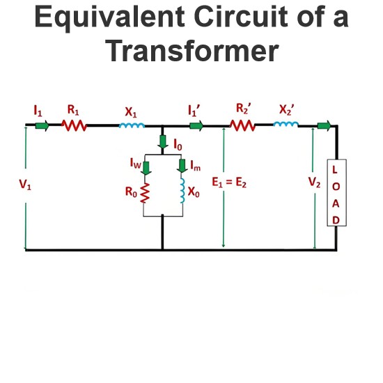
Equivalent Circuit of a Transformer
The equivalent circuit diagram of any device can be extremely useful for predicting how the device will behave under different operating conditions. It is essentially a circuit - based depiction of the equations that describe the device's performance.The simplified equivalent circuit of a transformer is constructed by representing all of the transformer's parameters on either the secondary side or the primary side. The equivalent circuit diagram of the transformer is presented below:Let the equi
Edwiin
06/03/2025
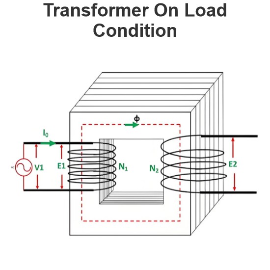
Transformer On Load Condition
Transformer Operation Under Load ConditionsWhen a transformer is under load, its secondary winding connects to a load, which can be resistive, inductive, or capacitive. A current I2 flows through the secondary winding, with its magnitude determined by the terminal voltageV2and load impedance. The phase angle between the secondary current and voltage depends on the load characteristics.Explanation of Transformer Load OperationThe operational behavior of a transformer under load is detailed as fol
Edwiin
06/03/2025
