Pole Changing Method
Pole Changing Method for Induction Motor Speed Control
The pole changing method stands as one of the primary techniques for regulating the speed of an induction motor. This approach to speed control through pole changing is predominantly applied to cage motors. The reason lies in the unique characteristic of the cage rotor, which automatically generates a number of poles that precisely match the number of poles in the stator winding.
There are three main methods by which the number of stator poles can be altered:
Multiple stator windings
Method of consequent poles
Pole amplitude modulation (PAM)
Each of these pole changing methods is explained in detail below:
Multiple Stator Winding
In the multiple stator winding method, two distinct windings are installed on the stator, each wound to create a different number of poles. Only one of these windings is powered at any given time. For instance, consider a motor equipped with two windings designed for 6 - pole and 4 - pole configurations. With an electrical supply frequency of 50 hertz, the corresponding synchronous speeds for these pole numbers would be 1000 revolutions per minute and 1500 revolutions per minute, respectively. However, this speed control method has its drawbacks; it is less energy - efficient and generally more expensive to implement compared to other techniques.
Method of Consequent Pole
The method of consequent poles involves dividing a single stator winding into several coil groups, with the terminals of each group brought out for external connection. By simply reconfiguring the connections between these coil groups, the number of poles can be effectively changed. In practical applications, stator windings are typically divided into just two coil groups, allowing for a pole number change in a ratio of 2:1.
The following figure illustrates a single phase of a stator winding that comprises 4 coils. These coils are split into two groups, labeled as a - b and c - d.
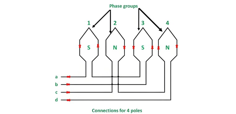
The a - b coil group is composed of an odd number of coils, specifically coils 1 and 3, while the c - d coil group contains an even number of coils, namely coils 2 and 4. These two coils within each group are connected in series. As depicted in the figure above, the terminals a, b, c, and d are brought out for external connections.
The flow of current through these coils can be controlled by connecting the coil groups either in series or in parallel, as illustrated in the figure below. This strategic connection arrangement allows for the manipulation of the magnetic field generated by the stator windings, which in turn plays a crucial role in altering the number of poles and thus regulating the speed of the induction motor.

In a 50 - hertz electrical system, when the stator winding configuration results in a total of four poles, the corresponding rotational speed of the induction motor is 1500 revolutions per minute (rpm).
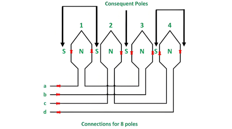
As depicted in the figure below, when the direction of the current flowing through the coils of group a - b is reversed, a significant change occurs in the magnetic field generated by the stator windings. Under this new condition, all the coils within the winding will produce north (N) poles. This alteration in the pole configuration directly impacts the motor's speed and operating characteristics, forming a key principle in the pole - changing method of speed control for induction motors.
Pole - Changing Principles and PAM Technique
For the magnetic circuit to be completed, the magnetic flux of the pole group must traverse the space between the pole groups. As a result, a magnetic pole of opposite polarity, an S - pole, is induced. These induced poles are referred to as consequent poles. Consequently, the number of poles in the machine doubles from its original count (for example, increasing from 4 to 8 poles), and the synchronous speed is halved (decreasing from 1500 rpm to 750 rpm).
This principle can be applied across all three phases of an induction motor. By carefully selecting combinations of series and parallel connections for the coil groups within each phase, and by choosing appropriate star or delta connections between the phases, it becomes possible to achieve speed changes while maintaining constant torque, constant power operation, or enabling variable torque operation.
Pole Amplitude Modulation (PAM) Technique
Pole amplitude modulation offers a highly adaptable approach to pole changing. Unlike some traditional methods that mainly achieve a 2:1 speed ratio, PAM can be utilized in scenarios where different speed ratios are needed. Motors specifically engineered for speed adjustment using the pole amplitude modulation scheme are called PAM motors. These motors provide enhanced flexibility in speed control, making them suitable for a wide range of applications where precise and varied speed regulation is required.
The Electricity Encyclopedia is dedicated to accelerating the dissemination and application of electricity knowledge and adding impetus to the development and innovation of the electricity industry.
