How do I identify the six unmarked leads of an induction motor?
The following methods can be used to identify the six unmarked leads of an induction motor:
Multimeter resistance measurement method
Battery phasing method: Connect the DC milliampere range of the multimeter to one of the windings. For example, connect the positive and negative poles of the multimeter to the two wires of the winding. Then, use a dry cell. Connect the negative pole of the battery to one of the wires of the winding, and use the positive pole of the battery to touch the other wire.If the pointer of the multimeter deflects forward, it means that the wire connected to the positive pole of the battery and the wire connected to the positive pole of the multimeter are either both head ends or both tail ends. If the pointer deflects backward, it means that one of the wires connected to the positive pole of the battery and the wire connected to the positive pole of the multimeter is the head end and the other is the tail end. Use the same method to judge the other two groups of windings.
Residual magnetism method: For a motor that has been used and has residual magnetism, the residual magnetism can be used to judge the head and tail ends of the winding. First, arbitrarily assume that the two wire ends of a certain group of windings are the head end and the tail end respectively, and connect the three assumed head ends together, and also connect the three assumed tail ends together. Then, set the multimeter to the milliampere or microampere range. Connect the two test leads of the multimeter to the connection lines of the head ends and tail ends. Slowly rotate the rotor of the motor by hand. If the pointer of the multimeter basically does not move, it means that the original assumption is correct. If the pointer swings greatly, it means that the original assumption is wrong. Reverse the two wire ends of the winding and retest until the pointer of the multimeter basically does not move.
Grouping: Set the multimeter to an appropriate resistance range (generally choose a smaller range. If the resistance value is relatively small, switch to a smaller range such as the milliohm range). Use the test leads of the multimeter to touch any two of the six leads. When a certain resistance value is measured (usually several ohms to several tens of ohms. The specific resistance value varies depending on the motor power and model) and the resistance value is relatively stable, these two wires belong to the same phase winding. In this way, the six leads can be divided into three groups, assumed to be U phase, V phase, and W phase.
Determine the head and tail ends of the same phase winding: After determining the three groups of windings, it is necessary to further determine the head and tail ends of each phase winding. There are various methods, such as:
Voltage measurement method
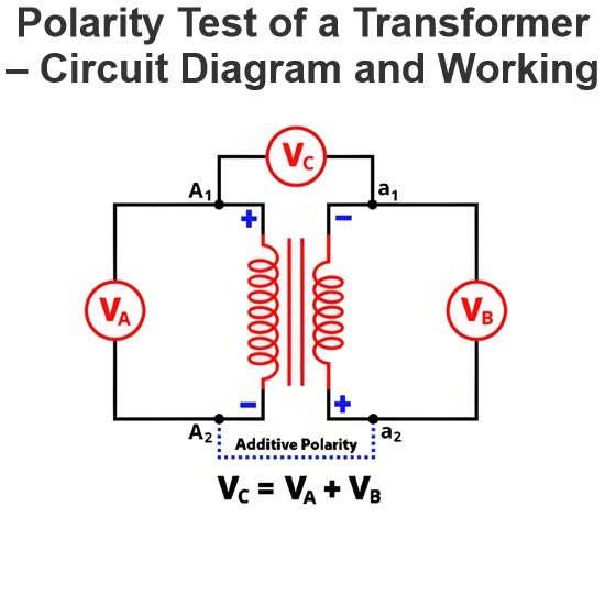
Winding connection: After finding the three groups of windings with the resistance range of the multimeter, connect two of the windings in series, and connect an AC voltmeter (select a range according to the rated voltage of the motor. Generally, a smaller range can be selected for testing first. If the voltage value exceeds the range, replace it with an appropriate range) across the two ends of the other winding.
Determine the head and tail ends: Apply a lower AC voltage (for example, a safety voltage of several tens of volts. The specific voltage value can be selected according to the actual situation, but it must be ensured that the motor will not be damaged) to the two series-connected windings. If the voltmeter has a reading, it means that these two windings are connected head to tail. If the voltmeter has no reading or the reading is very small, it means that these two windings may be connected tail to tail or head to head. Through this method, the head-tail relationship of two of the windings can be determined. Then, according to the connection relationship between the two windings that have been determined and the third winding, further determine the head and tail ends of the third winding.
Inductance measurement method (suitable for those with certain experience and professional equipment): Use an inductance measuring instrument to measure the inductance value between each lead and other leads respectively. The inductance value between the two leads of the same phase winding will be relatively large, while the inductance value between the leads of different phase windings will be relatively small. By measuring and comparing inductance values, it can be determined which leads belong to the same phase winding, and then further determine the head and tail ends of each phase winding. However, this method requires professional inductance measuring equipment and may not be commonly used in general maintenance sites.
During the above operations, ensure the safety of the operation to avoid dangers such as electric shock. If you are not familiar with or uncertain about the operation process, it is best to have a professional electrician or technician perform the operation.
The Electricity Encyclopedia is dedicated to accelerating the dissemination and application of electricity knowledge and adding impetus to the development and innovation of the electricity industry.


