Armature Reaction in Alternators
Armature Reaction Definition
Armature reaction in an alternator is defined as the effect of the armature’s magnetic field on the main magnetic field of the alternator or synchronous generator.
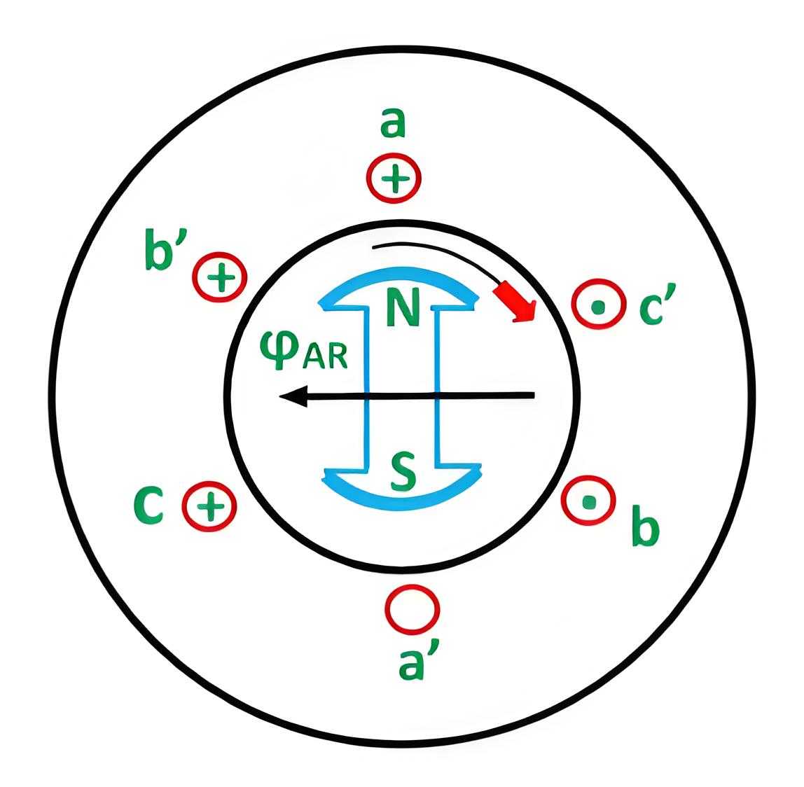
Magnetic Field Interaction
When the armature carries current, its magnetic field interacts with the main field, causing either distortion (cross-magnetizing) or reduction (demagnetizing) of the main field flux.
Power Factor Influence
At unity power factor, the angle between armature current I and induced emf E, is zero. That means, armature current and induced emf are in same phase. But we know theoretically that emf induced in the armature is due to changing main field flux, linked with the armature conductor.
As the field is excited by DC, the main field flux is constant in respect to field magnets, but it would be alternating in respect of armature as there is a relative motion between field and armature in the alternator. If main field flux of the alternator in respect of armature can be represented as
Then induced emf E across the armature is proportional to, dφf/dt.

Hence, from these above equations (1) and (2) it is clear that the angle between, φf and induced emf E will be 90o.

Now, armature flux φa is proportional to armature current I. Hence, armature flux φa is in phase with armature current I.
Again at unity electrical power factor I and E are in same phase. So, at unity power factor, φa is phase with E. So at this condition, armature flux is in phase with induced emf E and field flux is in quadrature with E. Hence, armature flux φa is in quadrature with main field flux φf.
As this two fluxes are perpendicular to each other, the armature reaction of the alternator at unity power factor is purely distorting or cross-magnetising type.
As the armature flux pushes the main field flux perpendicularly, distribution of main field flux under a pole face does not remain uniformly distributed. The flux density under the trailing pole tips increases somewhat while under the leading pole tips it decreases.
Lagging and Leading Loads
At leading power factor condition, armature current “I” leads induced emf E by an angle 90o. Again, we have shown just, field flux φf leads, induced emf E by 90o.
Again, armature flux φa is proportional to armature current I. Hence, φa is in phase with I. Hence, armature flux φa also leads E, by 90o as I leads E by 90o.
As in this case both armature flux and field flux lead, induced emf E by 90o, it can be said, field flux and armature flux are in the same direction. Hence, the resultant flux is simply arithmetic sum of field flux and armature flux. Hence, at last, it can be said that armature reaction of alternator due to a purely leading electrical power factor is the magnetizing type.
Unity Power Factor Effect
The armature reaction flux is constant in magnitude and rotates at synchronous speed.
The armature reaction is cross magnetising when the generator supplies a load at unity power factor.
When the generator supplies a load at leading power factor the armature reaction is partly demagnetising and partly cross-magnetising.
When the generator supplies a load at leading power factor the armature reaction is partly magnetising and partly cross-magnetising.
Armature flux acts independently of main field flux.
The Electricity Encyclopedia is dedicated to accelerating the dissemination and application of electricity knowledge and adding impetus to the development and innovation of the electricity industry.
