What is the Working Principle of Alternator?
What is the Working Principle of Alternator?
Alternator definition
An alternator is a machine that uses electromagnetic induction to convert mechanical energy into alternating current electricity.
Working principle
The alternator works on the basis of Faraday's Law, in which motion between a conductor and a magnetic field induces an electric current.
Induction process
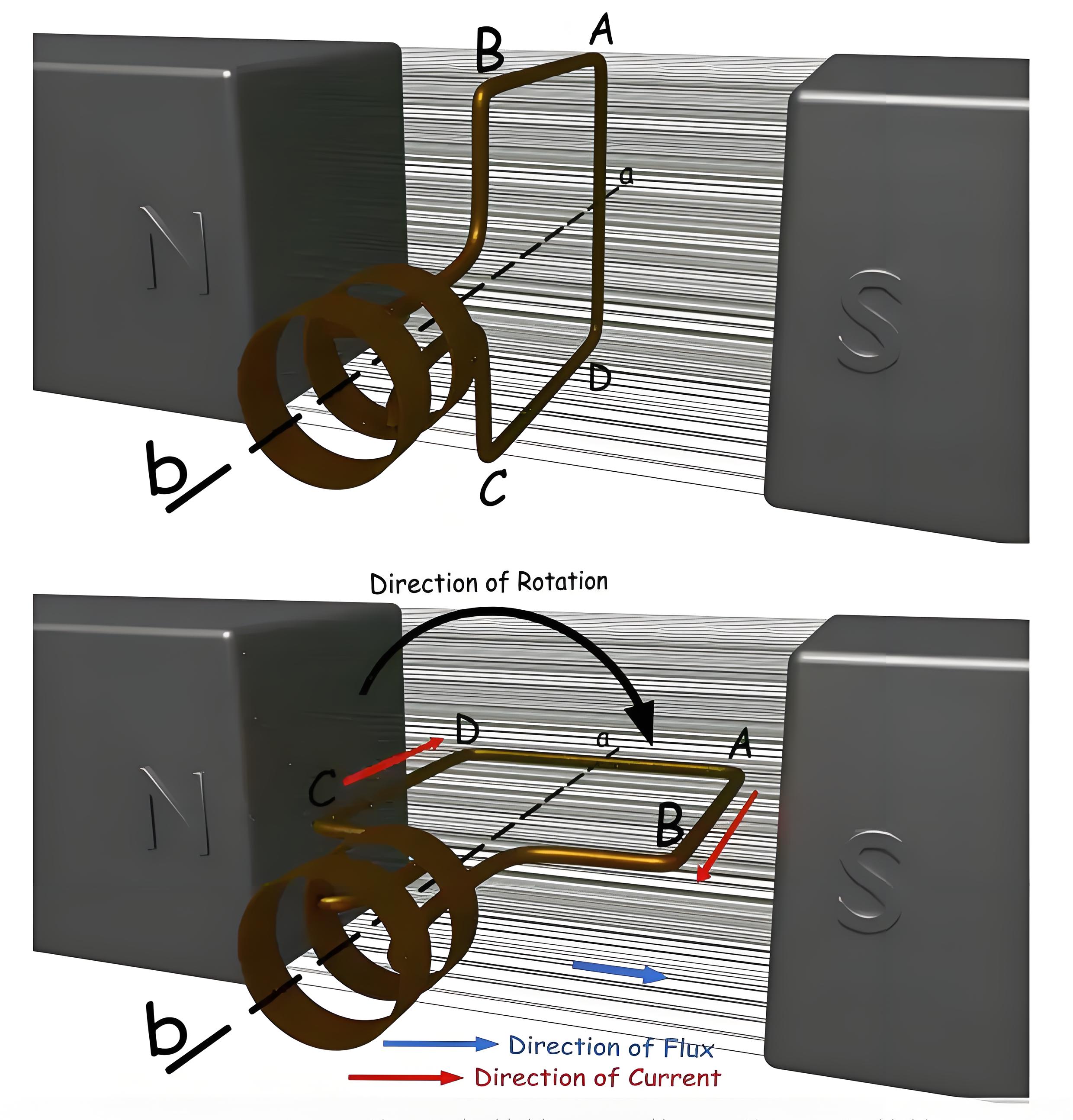
Suppose that this one-turn cycle ABCD can be rotated against axes a-b. Let's say the cycle starts spinning clockwise. Post-90 o rotation: One side of the loop AB or conductor AB is located in front of the S pole and conductor CD is located in front of the N pole. At this position, the tangential motion of conductor AB is just perpendicular to the flux line from the N to the S poles. Therefore, the flux cutting rate of conductor AB is the largest here, and for this flux cutting, conductor AB will generate an induced current, the direction of which can be determined by Fleming's right hand rule. According to this rule, the direction of this current will be from A to B. At the same time, the conductor CD is located below the N pole, and here also if we apply Fleming's right hand rule, we will find the direction of the induced current, which will go from C to D.
After a further clockwise rotation of 90 degrees, the ring ABCD reaches a vertical position. Here, the motion of the conductors AB and CD are aligned parallel to the flux lines, so the magnetic flux is not cut and therefore no current is generated.
Alternating current
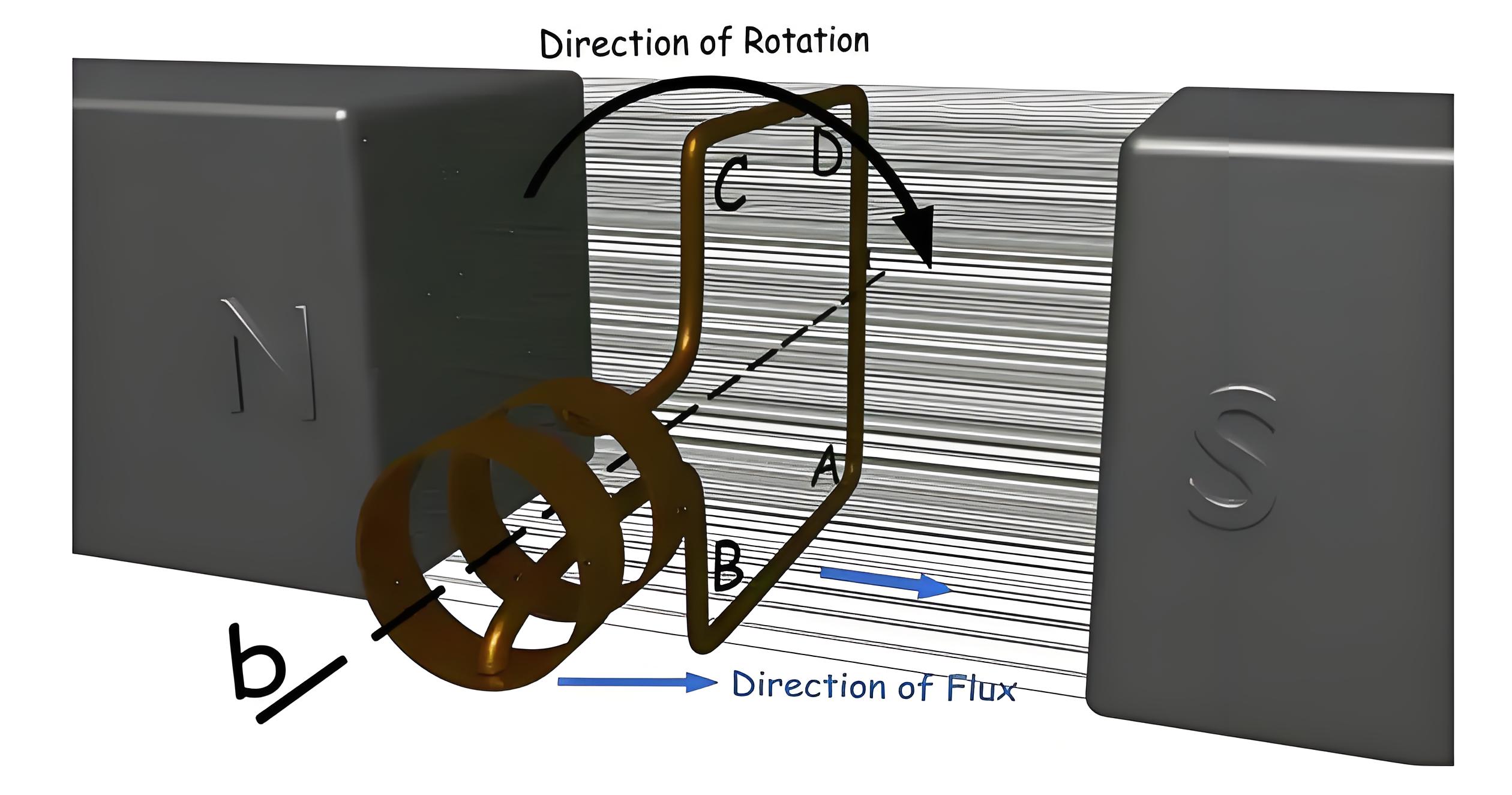
After another 90 turns clockwise, o turns again to the horizontal position, where conductor AB is under pole N and CD is under pole S. Here if we apply Fleming's right hand rule again, we will see that the induced current in conductor AB is from point B to A, and the induced current in conductor CD is from D to C.
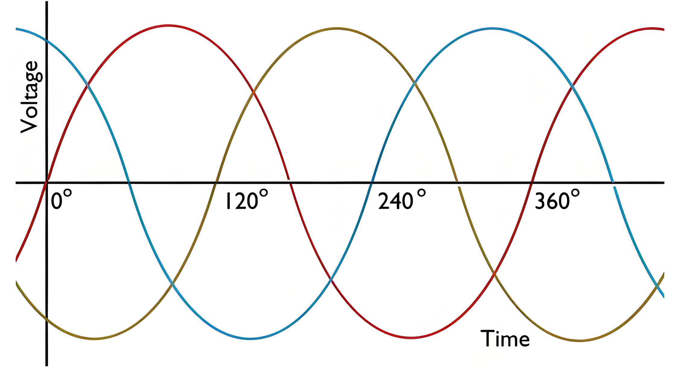
As the loop moves from vertical to horizontal, the current in the conductor increases from zero to a maximum. Current flows from B to A, A to D, D to C, C to B, from A to B, B to C, C to D, and D to A in a closed loop. When the loop again approaches the vertical position, the current drops to zero. As it continues to rotate, the current changes direction. Each full turn causes the current to peak, drop to zero, peak in the opposite direction, and then return to zero, completing one sine wave cycle per 360 degrees of rotation. The process illustrates how alternating current can be generated by rotating a conductor in a magnetic field.
Practical configuration
Modern alternators typically have fixed armatures and rotating magnetic fields that increase the efficiency of generating three-phase alternating current for a wide range of power distribution.
The Electricity Encyclopedia is dedicated to accelerating the dissemination and application of electricity knowledge and adding impetus to the development and innovation of the electricity industry.
