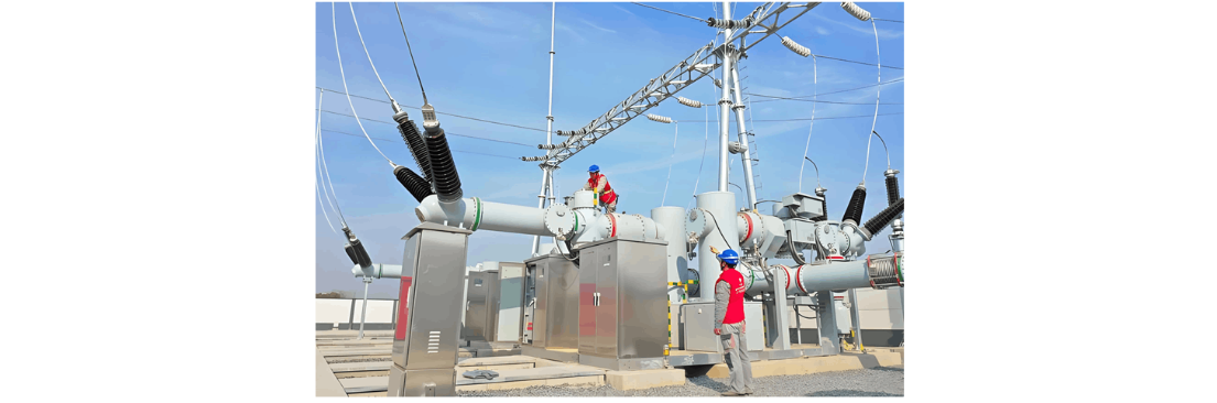
The core advantages of IEC 62271 - 203 Certified GIS equipment lie in its compact design and excellent electrical performance, enabling it to undertake the transmission and distribution of high - voltage current within a limited space. Therefore, during the installation in 110 kV substations, precise consideration must be given to equipment configuration, spatial layout, and compatibility with existing systems.
Firstly, before installation, the dimensions of the pre - determined installation location should be measured, and it should be ensured that this location can meet the environmental requirements for the equipment's operation, such as temperature, humidity, and seismic performance. This step is crucial, as the performance of IEC 62271 - 203 Certified GIS equipment is significantly affected by the installation environment.
Secondly, a careful plan for the electrical installation scheme should be made to ensure that all electrical connections are carried out in strict accordance with the manufacturer's specifications and comply with the safety standards of the State Grid. This includes the design and layout of the grounding system, cable routes, and protection systems for IEC 62271 - 203 Certified GIS equipment. Each aspect must be accurately implemented to avoid any potential safety risks.
GIS Equipment Installation Technology
Equipment Transportation and Preparation
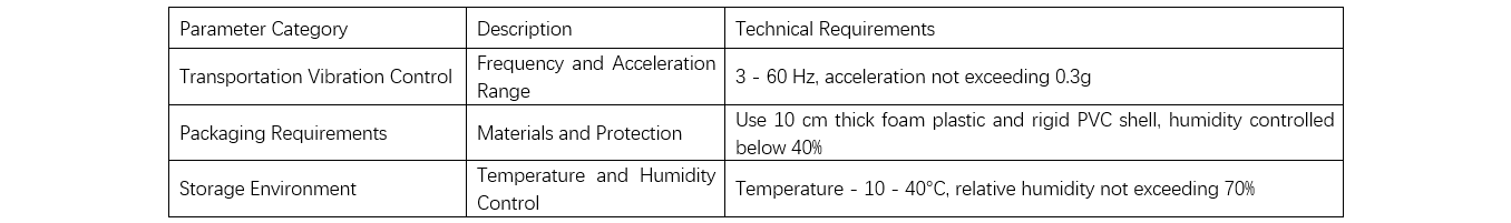
During transportation, GIS equipment—comprising heavy metal enclosures (typically several tons) and sensitive electrical components—requires vibration control within 3–60 Hz and acceleration ≤0.3g (gravitational acceleration). Transport protocols must adhere to electrical equipment standards to minimize shocks to sensitive components and reduce pre - installation failure rates.
Packaging should utilize vibration - resistant and waterproof materials. For example, main switches must be fully wrapped in ≥10 cm thick foam and reinforced with rigid PVC shells, following manufacturer specifications. Desiccants should maintain internal humidity ≤40% to prevent moisture ingress.
Storage conditions mandate temperature control between - 10°C and 40°C with relative humidity ≤70% to protect metal and insulation materials. Storage areas must be shielded from electromagnetic interference, dust, and corrosive agents. Given GIS equipment weights often exceeding 25 tons, lifting equipment must have a ≥30 - ton capacity with stability meeting construction requirements. Handling speeds should not exceed 2 m/min to avoid impact damage.
Pre - installation on - site testing is critical, including insulation resistance, grounding resistance, and phase checks. All results must comply with standards to ensure equipment performance meets design specifications. Technical requirements for transportation and preparation are detailed in Table 1. Additionally, the 145kV circuit breaker price is a key factor in procurement and overall project cost evaluation.
Equipment Handling and Positioning
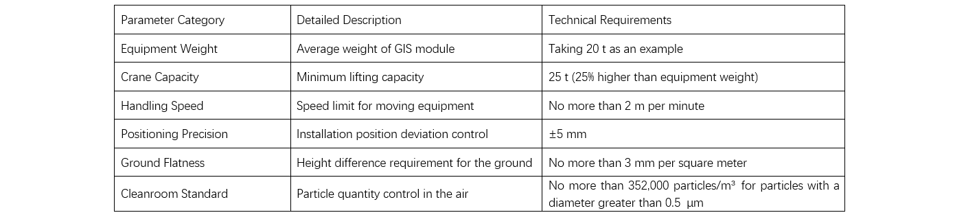
When moving GIS equipment, the design load of general lifting equipment is usually more than 25% higher than the self-weight of the equipment to ensure a safety margin during the moving process . For example, when the weight of the GIS module is 20 tons, then the crane adopted needs to have a lifting capacity of at least 25 tons. At the same time, the stability of the crane should be evaluated to prevent it from toppling over due to load deviation during operation. During the actual transportation process of GIS equipment, the transportation speed should not exceed 2 m/min. This can reduce the vibration and potential damage of the equipment caused by excessive speed. Before each move, it is necessary to check whether there is sufficient space and stable support surface on the path to avoid equipment tilting or falling due to operation on uneven ground. In the positioning process, accuracy is a crucial factor. The positional deviation of installing GIS equipment must be controlled within ± 5mm to ensure the correct connection of equipment interfaces and the integrity of the system. The realization of this precision is usually assisted by high-precision laser rangefinders and electronic levels for positioning.The preparatory work at the installation point includes the measurement of the flatness of the ground, with a standard of no more than 3mm in height difference per square meter. The environmental requirement for installing GIS equipment is that the number of particles with a diameter greater than 0.5 μm in the air of the installation area shall not exceed 352,000 per cubic meter. For this reason, a temporary cleanroom environment is usually set up at the installation site, and high-efficiency particulate air (HEPA) filters are used to maintain air quality and prevent dust and particles from entering the equipment during the installation process. The technical requirements for equipment handling and positioning are shown in Table 2.
Component Assembly
The joints of components must have extremely high sealing performance to prevent gas leakage. For GIS equipment, the annual leakage rate of SF₆ gas should not exceed 0.5%. This indicator is directly related to the insulation strength and arc - resistance ability of the equipment. To meet this requirement, the sealing gasket material used in the assembly process must have excellent temperature - resistant and pressure - resistant properties. Moreover, the compression setting of the gasket should be 35% - 50% to ensure long - term sealing effectiveness.
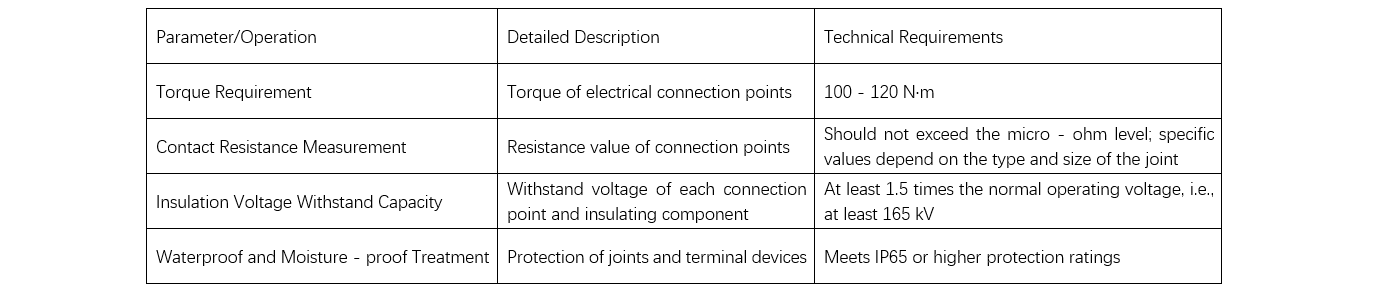
During the specific operation of component assembly, all connection points must be tightened with a torque wrench according to the torque specified by the manufacturer. For example, for the connecting bolts that mainly carry current, the torque should be 100 - 120 N·m to ensure the stability and reliability of the electrical connection.
Electrical Connections
The primary task of electrical connections is to ensure that all conductive components and connection points exhibit sufficient electrical conductivity and mechanical stability. During the connection process, the torque at all electrical connection points must comply with the manufacturer - specified requirements to guarantee firm and long - term stable connections. All bolts and contact surfaces must undergo appropriate cleaning and pre - treatment, typically involving the removal of oxide layers and the application of conductive lubricants to reduce contact resistance.
Measuring contact resistance is a crucial step in the quality control of electrical connections. The contact resistance at connection points should not exceed the micro - ohm level, with specific values determined according to the type and size of the joint [5]. To meet this standard, each connection point must be tested using a precision resistance tester to ensure that all connections fall within the specified resistance range.
In high - voltage environments, electrical insulation is also a vital aspect of electrical connections. Each connection point and insulating component must withstand at least 1.5 times the normal operating voltage. For 110 kV GIS equipment, this means withstanding a minimum of 165 kV. Waterproofing and moisture - proofing treatments for all electrical connections are essential, especially for substation facilities operating in outdoor or humid environments. Joints and terminal devices should employ sealing technologies that meet IP65 or higher protection ratings to prevent moisture and contaminants from entering the electrical system. Key technical requirements for electrical connections are shown in Table 3.
Commissioning Tests
Commissioning tests generally start with unit - level tests and gradually progress to overall system tests. In insulation resistance tests, the objective is to ensure that all electrical insulation materials remain in good condition and are free from potential damage incurred during the installation process. To assess the insulation strength of GIS equipment, withstand voltage tests are necessary. For 110 kV GIS equipment, the AC test voltage applied in the withstand voltage test is at least 230 kV, with a duration of 1 minute, to examine the system's performance under high - voltage conditions.
Partial discharge (PD) tests are of particular importance for evaluating the safety of GIS equipment. Partial discharge is an early sign of insulation material degradation. Therefore, monitoring and controlling PD activity is crucial for preventing equipment failures. The amount of discharge recorded during the test should not exceed 5 pC. PD tests are conducted using acoustic emission detection devices at specific frequencies to ensure that all detected discharge activities are properly identified and evaluated.
Mechanical operation tests of circuit breakers are also part of the commissioning tests. These involve multiple consecutive opening and closing operations of the circuit breakers. Typically, at least 50 mechanical operations without failure are required to verify their operational reliability. The time for each operation is recorded and compared with the standard operation time provided by the manufacturer, which is usually between 30 - 50 ms. System synchronization tests are also indispensable. This test is used to verify the synchronous performance of components such as circuit breakers and disconnectors during actual operations. The synchronization error must be controlled within ±10 ms to ensure that all operations are completed smoothly within the time window required by the power grid.
Finally, overall system function tests are carried out, including the inspection of protection and control systems. This step ensures that all protective relays, control modules, and communication devices can correctly respond to preset fault and operating conditions. Various fault scenarios are simulated during the test to verify the system's response time and action accuracy. The reaction time for all actions is generally required to be within 100 ms.
Conclusion
The application of GIS equipment in 110 kV substations not only optimizes the existing installation process and enhances the overall system performance but also provides strong support for technological advancements in the power industry. By delving into the installation techniques of GIS equipment, valuable reference materials can be provided for designers. This enables them to make more scientific and effective decisions when facing complex engineering challenges, thereby improving the success rate of substation projects.