What is a Varactor Diode?
What is a Varactor Diode?
Varactor Diode
A varactor diode is defined as a reverse-biased p-n junction diode whose capacitance can be varied electrically. These diodes are also known as varicaps, tuning diodes, voltage variable capacitor diodes, parametric diodes, and variable capacitor diodes.
The operation of the p-n junction depends on the type of bias applied, either forward or reverse. In forward bias, the width of the depletion region decreases as the voltage increases.
On the other hand, the width of the depletion region is seen to increase with an increase in the applied voltage for the reverse bias scenario.
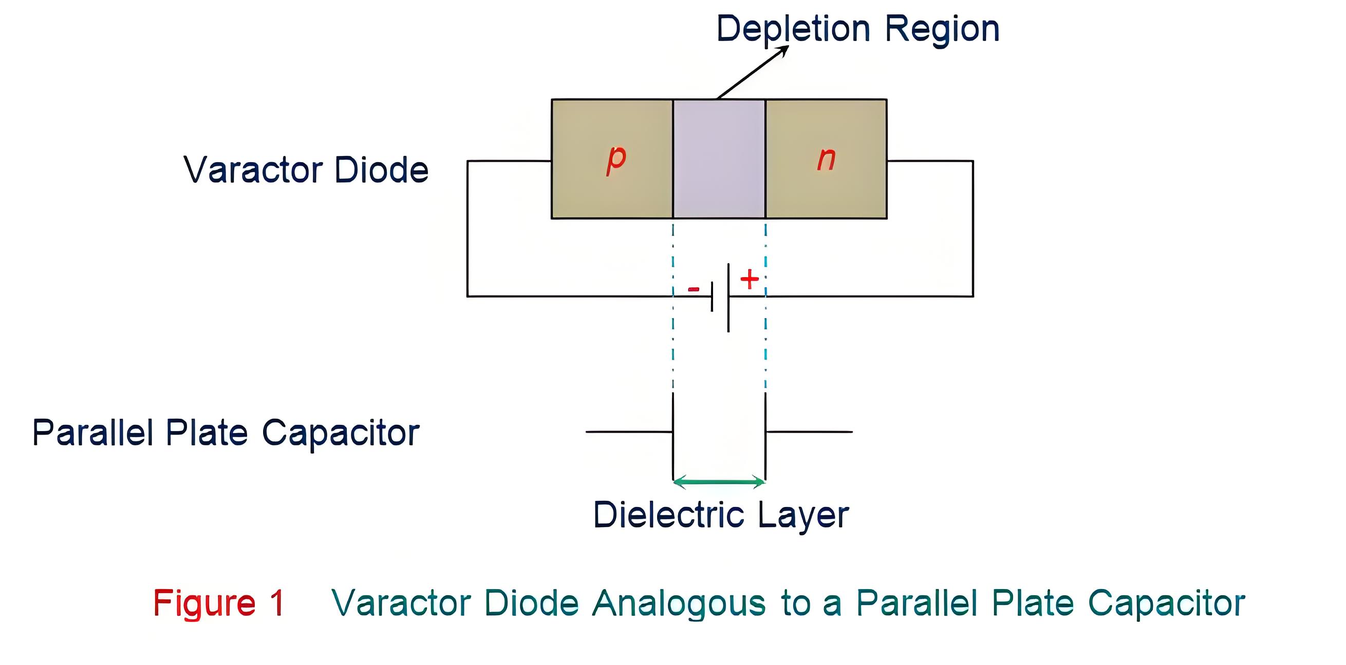
In reverse bias, the p-n junction behaves like a capacitor. The p and n layers act as the capacitor’s plates, and the depletion region serves as the dielectric separating them.
Therefore, the formula for calculating the capacitance of a parallel plate capacitor can also be applied to the varactor diode.
The capacitance of a varactor diode can be expressed mathematically as:

Where,
Cj is the total capacitance of the junction.
ε is the permittivity of the semiconductor material.
A is the cross-sectional area of the junction.
d is the width of the depletion region.
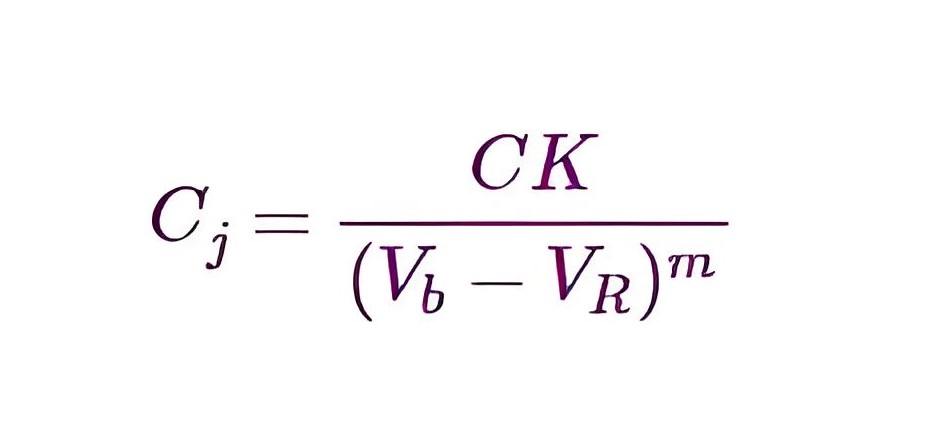
Further, the relationship between the capacitance and the reverse bias voltage is given as
Where,
Cj is the capacitance of the varactor diode.
C is the capacitance of the varactor diode when unbiased.
K is the constant, often considered to be 1.
Vb is the barrier potential.
VR is the applied reverse voltage.
m is the material-dependent constant.
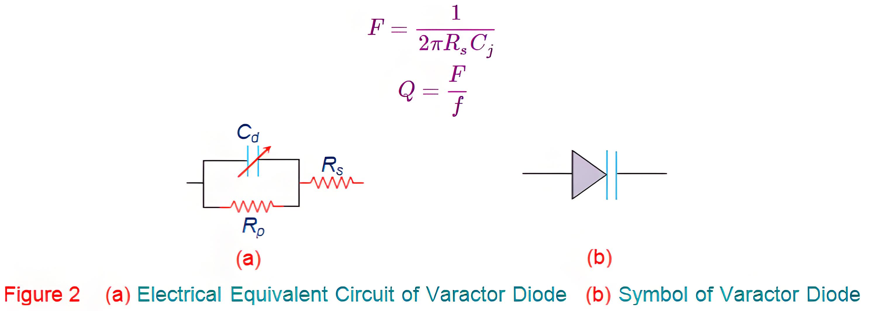
In addition, the electrical circuit equivalent of a varactor diode and its symbol is shown in Figure 2.
This indicates that the maximum operating frequency of the circuit is dependent on the series resistance (Rs) and the diode capacitance, which can be mathematically given as
In addition, the quality factor of the varactor diode is given by the equation
Where, F and f represent the cut-off frequency and the operating frequency, respectively.
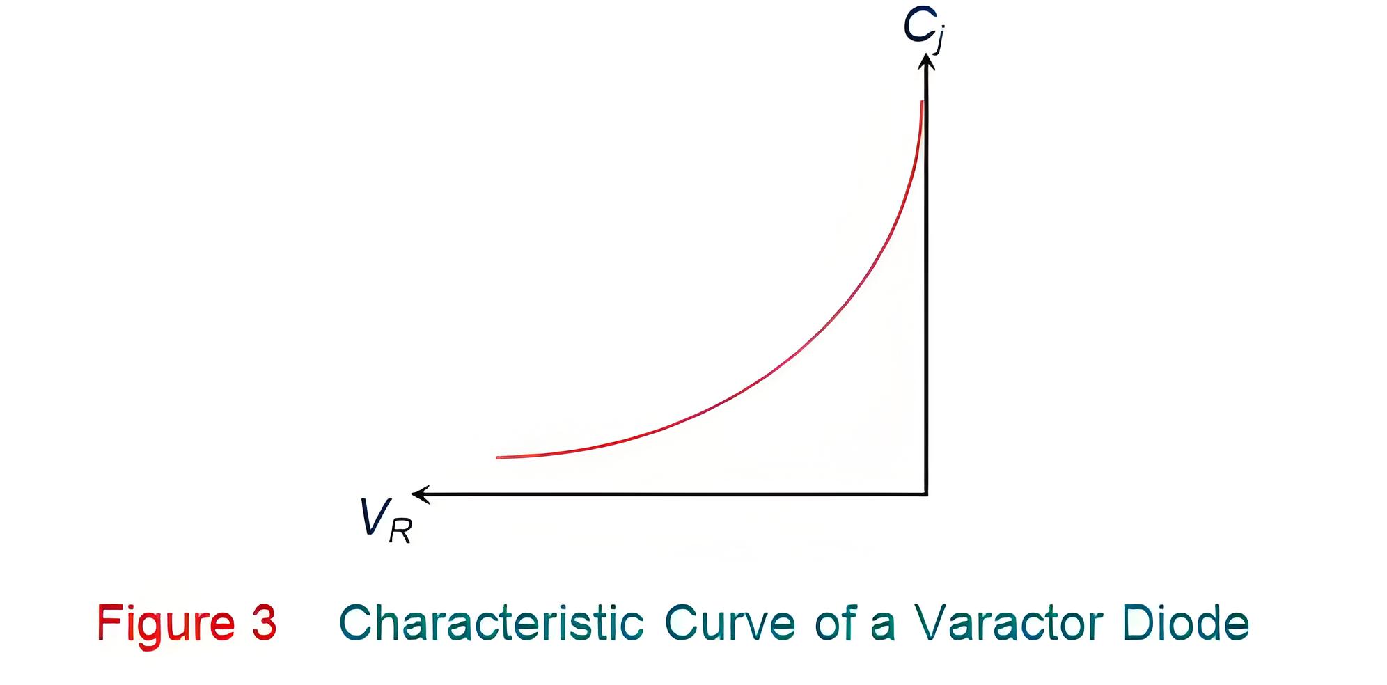
As a result, one can conclude that the capacitance of the varactor diode can be varied by varying the magnitude of the reverse bias voltage as it varies the width of the depletion region, d. Also it is evident from the capacitance equation that d is inversely proportional to C. This means that the junction capacitance of the varactor diode decreases with an increase in the depletion region width caused to due to an increase in the reverse bias voltage (VR), as shown by the graph in Figure 3. Meanwhile it is important to note that although all the diodes exhibit the similar property, varactor diodes are specially manufactured to achieve the objective. In other words varactor diodes are manufactured with an intention to obtain a definite C-V curve which can be accomplished by controlling the level of doping during the process of manufacture. Depending on this, varactor diodes can be classified into two types viz., abrupt varactor diodes and hyper-abrupt varactor diodes, depending on whether the p-n junction diode is linearly or non-linearly doped (respectively).
Applications
AFC circuits
Adjusting bridge circuits
Adjustable bandpass filters
Voltage Controlled Oscillators (VCOs)
RF phase shifters
Frequency multipliers
The Electricity Encyclopedia is dedicated to accelerating the dissemination and application of electricity knowledge and adding impetus to the development and innovation of the electricity industry.


