Applications of BJT
BJT Definition
A Bipolar Junction Transistor (BJT) is defined as a three-terminal semiconductor device used for amplification and switching.
Applications of Bipolar Junction Transistor
There are two types of applications of bipolar junction transistor, switching and amplification.
Transistor as a Switch
In switching applications, a transistor operates in either the saturation or cutoff region. In the cutoff region, the transistor acts as an open switch, while in saturation, it acts as a closed switch.
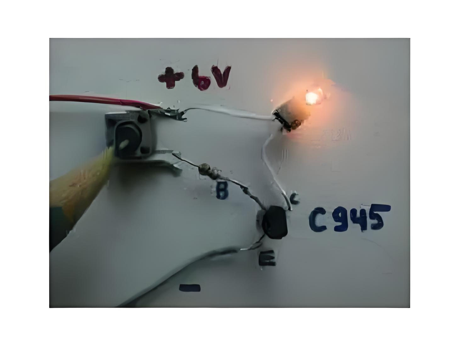
Open Switch
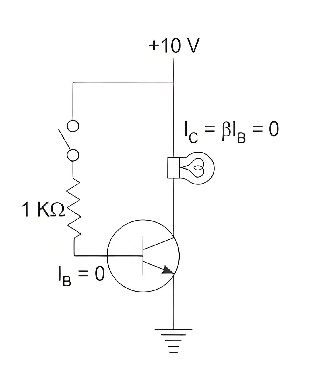
In the cutoff region (both junctions are reversed biased) the voltage across the CE junction is very high. The input voltage is zero so both base and collector currents are zero, hence the resistance offered by the BJT us very high (ideally infinite).
Closed Switch
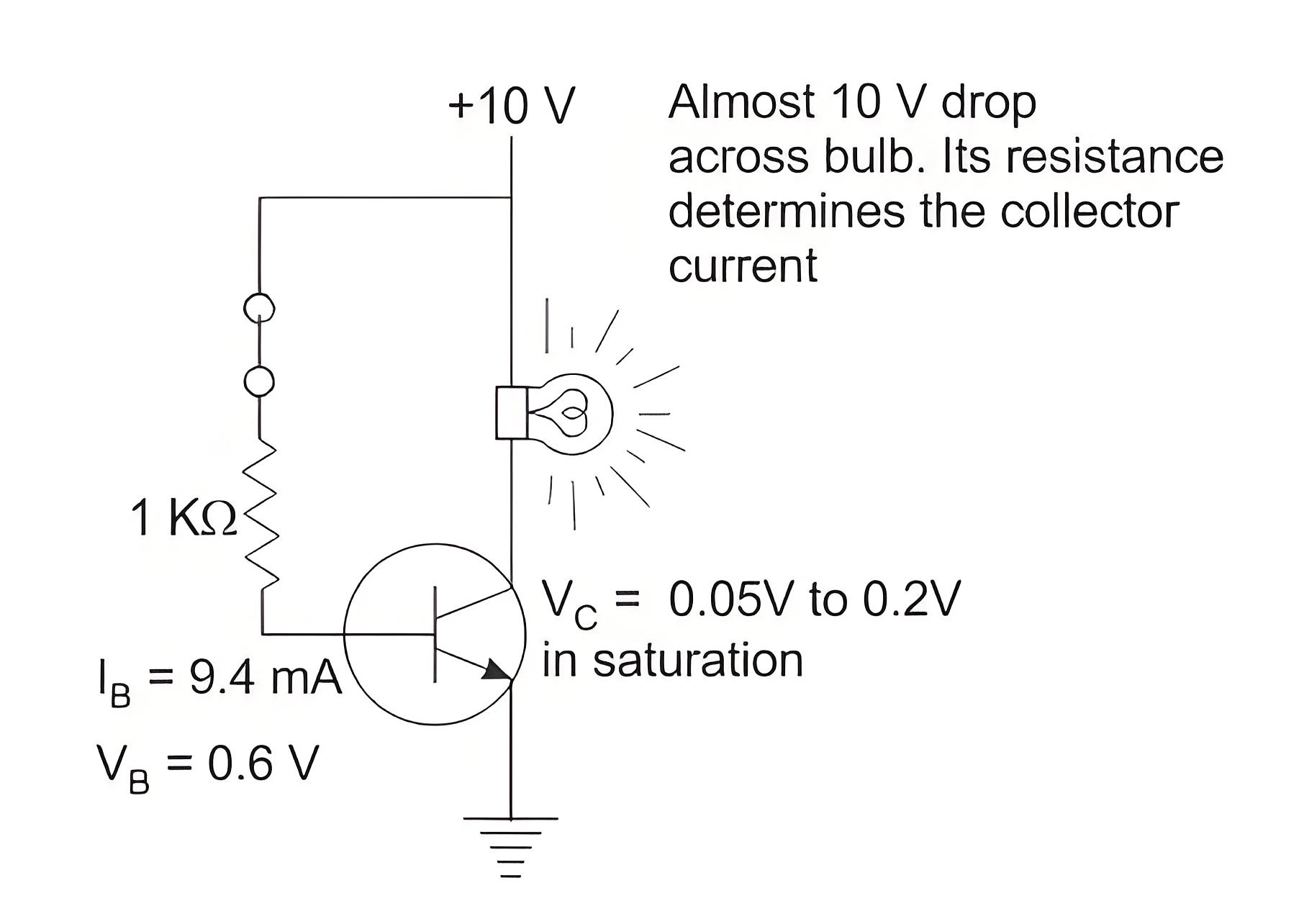
In saturation (both junctions are forward biased), a high input voltage is applied to the base, causing a large base current to flow. This results in a small voltage drop across the collector-emitter junction (0.05 to 0.2 V) and a large collector current. The small voltage drop makes the BJT act like a closed switch.
BJT as Amplifier
Single Stage RC Coupled CE Amplifier
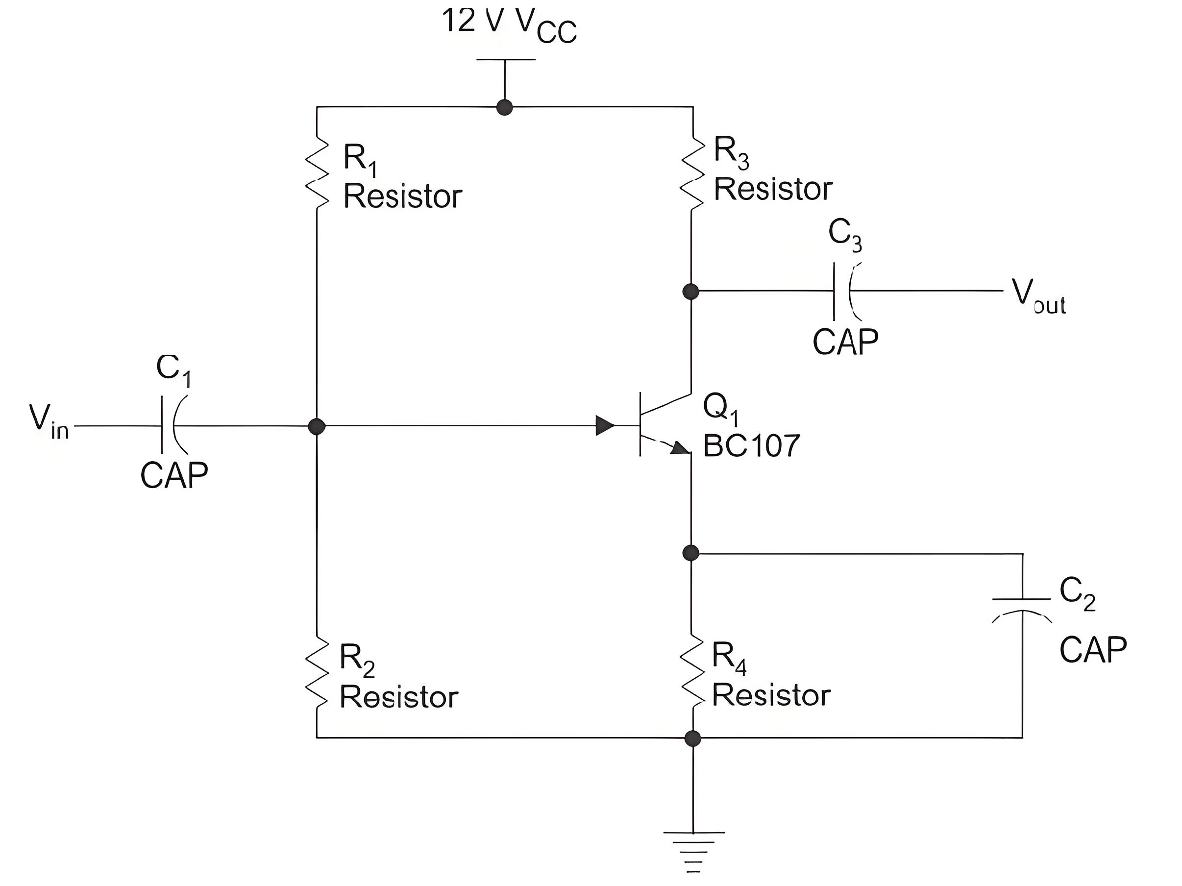
The figure shows a single stage CE amplifier. C1 and C3 are coupling capacitors, they are used for blocking the DC component and passing only ac part they also ensure that the DC basing conditions of the BJT remains unchanged even after input is applied. C2 is the bypass capacitor which increases the voltage gain and bypasses the R4 resistor for AC signals.
The BJT is biased in the active region using the necessary biasing components. The Q point is made stable in the active region of the transistor. When input is applied as shown below the base current starts to vary up and down, hence collector current also varies as I C = β × IB. Therefore voltage across R3 varies as the collector current is passing through it. Voltage across R3 is the amplified one and is 180o apart from the input signal. Thus voltage across R3 is coupled to the load and amplification has taken place. If the Q point is maintained to be at the center of the load very less or no waveform distortion will take place. The voltage as well as current gain of the CE amplifier is high (gain is the factor by which the voltage of current increases from input to output). It is commonly used in radios and as low frequency voltage amplifier.
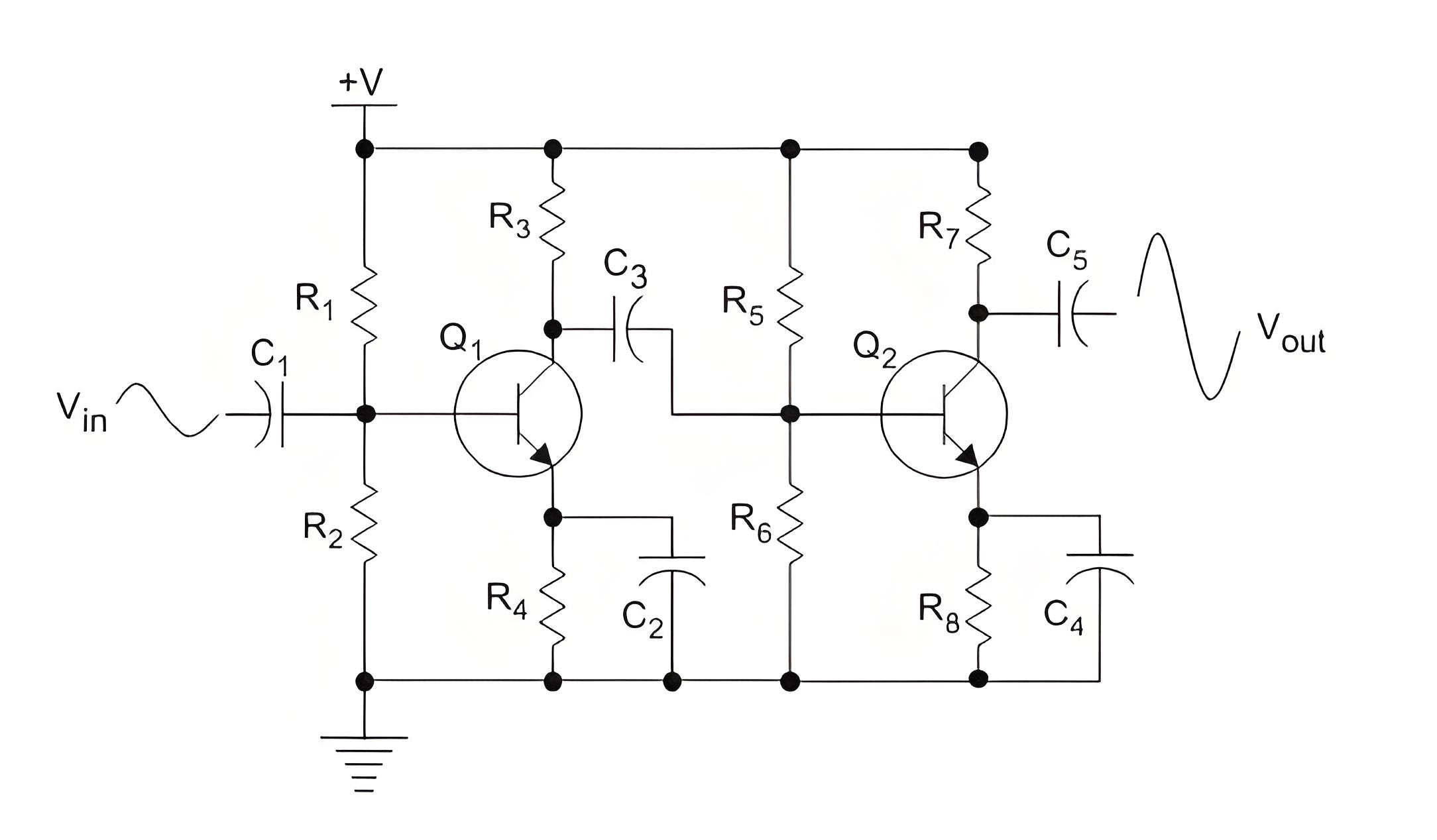
To further increase the gain multistage amplifiers are used. They are connected via capacitor, electrical transformer, R-L or directly coupled depending on the application. The overall gain is the product of gains of individual stages. Figure below shows a two stage CE amplifier.
The Electricity Encyclopedia is dedicated to accelerating the dissemination and application of electricity knowledge and adding impetus to the development and innovation of the electricity industry.
