High Voltage Gas Insulted Switchgear (GIS) Field Testing According to IEEE C37.122

High Voltage Gas Insulted Switchgear (GIS) Field Testing According to IEEE C37.122
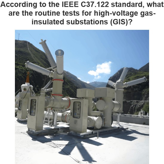
The final assembly of the gas - insulated substation (GIS) takes place in the field. This is where all the diverse components that make up the GIS are brought together for the first time. Even if it were possible to fully assemble the GIS in a factory, it would still have to be disassembled for transportation, shipped, and then reassembled at the installation site.
The objective of the field tests is to confirm that all GIS components function satisfactorily both electrically and mechanically after being assembled at the job site. These tests offer a means of demonstrating that the GIS apparatus has been correctly assembled and wired and will operate as expected.
- Mechanical Tests: Gas Leakage and Gas Quality (Moisture, Purity, and Density)
- Gas Leakage Test:All gas compartments of the GIS must be filled with sulfur hexafluoride gas (SF6) or the required gas mixture up to the manufacturer - specified rated filling pressure. Subsequently, a test is carried out to detect any gas leaks. An initial inspection is conducted to identify all potential gas leakage points and ensure compliance with the specified maximum gas leak rate. This gas leak test should cover all enclosure flanges, enclosure welds, as well as all gas monitoring devices, gas valves, and interconnecting gas piping that have been assembled at the job site.
- Moisture Content Measurement:The moisture content of the gas needs to be measured before the GIS is energized. To obtain a reliable measurement, the moisture content should be measured after a period of time following filling, as recommended by the manufacturer. The moisture content must not exceed the limit set by the manufacturer or the value agreed upon between the manufacturer and the user, whichever is lower.
- Gas Purity Verification:Prior to energization, the purity of the gas, expressed as a percentage of SF6, must be verified. The gas purity should meet the requirements specified by the manufacturer.
Gas Density Measurement:The density of the gas should be measured and confirmed to be in line with the manufacturer's nominal rated filling requirements.
2. Electrical Tests: Contact Resistance
- Main Current - Carrying Circuits:Contact resistance measurements of the main current - carrying circuits are required for each bus connecting joint, circuit breaker, disconnect switch, grounding switch, bushing, and power cable connection. These measurements are used to demonstrate and verify that the resistance values are within the specified limits.
GIS Enclosure Bonding - Connections (for Isolated Phase Bus):In cases where an isolated (single) - phase bus is utilized, contact resistance measurements also need to be performed on the GIS enclosure bonding connections. The resistivity measurements should not exceed the maximum permissible values as per IEEE Std C37.100.1.
3. Electrical Tests: Low - Frequency AC Voltage Withstand Test
Focused on the design of electrical equipment, proficient in electrical principles and relevant specifications, and skilled in using design software. From intelligent substations to various types of electrical equipment, I am adept at optimizing design solutions, integrating new technologies. With practical experience and collaborative management capabilities, I deliver outstanding electrical design achievements.