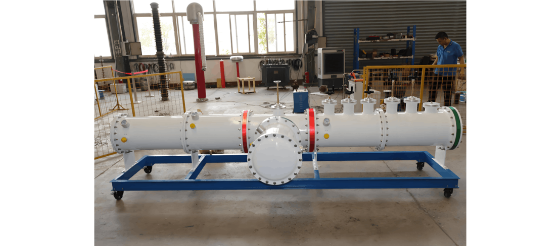
As required for routine tests of gas-insulated metal-enclosed switchgear, it is necessary to ensure that each equipment unit undergoes systematic routine tests before leaving the factory. These tests (also known as production tests) core on confirming the consistency between the equipment's operating status and design requirements as well as type-test parameters, serving as an indispensable quality control link after assembly. Test parameters are directly derived from type-test data, so routine test results must align with type-test data within specific tolerance ranges.
Implementation Specifications for Dielectric Tests
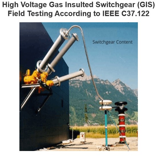
Dielectric tests shall be carried out after completing mechanical routine tests, aiming to verify the dielectric performance of GIS, ensure correct equipment assembly and qualified dielectric manufacturing quality of components, and inspect for internal particles or contaminants.
- Power Frequency Dielectric Test: Routine tests adopt the form of power frequency withstand voltage tests, excluding impulse tests such as lightning and switching impulse tests. Under the minimum functional SF₆ pressure, the following parts shall be tested: phase-to-ground, phase-to-phase (for three-phase-in-one-enclosure designs), and the breaks of open switching devices. The main criterion for passing the test is that the equipment can withstand the one-minute withstand voltage value without disruptive discharge.
- Partial Discharge Measurement: This item is used to detect material or manufacturing defects, and shall be conducted simultaneously with dielectric tests after mechanical routine tests, covering all components of GIS.
Requirements for Main Circuit Resistance Measurement
A 100A DC current shall be used to measure the voltage drop or resistance value of the main circuit, with the allowable deviation of test data from type-test data controlled within ±20%.
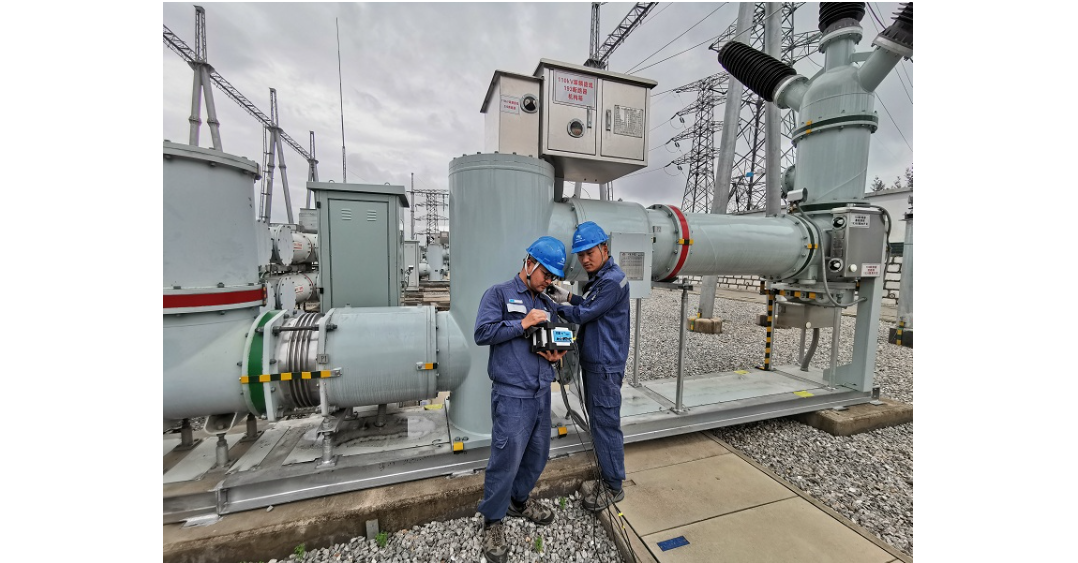
Operation Procedures for Tightness Tests
During the test, SF₆ pipelines, leakage detectors, full-area inspection tools for enclosure components, SF₆ pressure gauges, and density monitoring devices shall be used to inspect for leaks in all parts of the equipment.
Standards for Enclosure Pressure Tests
Enclosures shall undergo pressure tests after machining:
- The test pressure for welded aluminum and steel enclosures is 1.3 times the design pressure;
- The test pressure for cast enclosures is 2 times the design pressure.
Automated test stations can immediately perform tightness tests with helium after the enclosure pressure tests. The specific standards are as follows:
- Welded aluminum/steel enclosures: 1.3 times the design pressure;
- Cast aluminum/composite aluminum enclosures: 2 times the design pressure.
The test pressure shall be maintained for at least 1 minute, and no rupture or permanent deformation of the enclosure is allowed.
The above test procedures are all implemented in accordance with the IEEE C37.122 standard to ensure that the mechanical strength, dielectric performance, and sealing reliability of each GIS equipment meet the factory requirements.