Analysis of the Failure of a 750 kV Tank Type SF₆ Compressed Gas Circuit Breaker

Felix Spark
05/20/2025
Failure Phenomenon
Failure Information and Operational Mode Before Failure
Failure Information and Operational Mode Before Failure
At 17:53:50 on May 16, 2016, the protection devices of two sets on Jingchuan II Line operated successively. Phase B was selected for tripping, and the B - phase of circuit breakers 7522 and 7520 was opened. The protection of circuit breaker 7522 detected a permanent fault on the two - circuit line protection device, with a delay of 0.6s. Subsequently, the ABC three - phase of circuit breaker 7522 tripped.
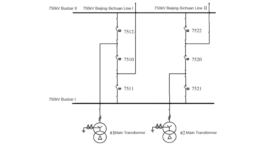
During this process, the failure protection of the B - phase of circuit breaker 7522 actuated the differential protection of Bus II, and circuit breaker 7512 was opened, resulting in the power outage of 750kV Bus II. The pre - failure system operation mode and unit operation conditions are shown in Figure 1. The active power of Unit #1 was 645MW, and that of Unit #2 was 602MW. Jingchuan I and II Lines were operating normally. The wiring mode of the step - up substation was 3/2 wiring, and the step - up substation was operating in a loop - closing mode.
Fault Inspection Situation
On - site Visual Inspection
On - site Visual Inspection
An on - site inspection of circuit breaker 7522 showed that the mechanical open/close indicators for phases A/B/C indicated the open position, which was at the "0" position. The hydraulic operating structure was in the spring compression position. For the WB - 2C circuit breaker, phases A/B/
For phase C, on - site inspection of the operation box panel showed that the red light of the TWJ indicator was on. The SF₆ gas pressure of the A/B/C three - phase circuit breakers was 0.62MPa (relative pressure), and there were no obvious abnormalities in circuit breaker 7522.
Protection Action Information
- Jingchuan II Line Protection IRCS - 931BM Protection Device: At 17:53:50:404 on May 16, 2016, the B - phase current differential protection operated. The current differential protection tripped phases A, B, and C at 767ms, and the tripping position contacts of phases A, B, and C returned at 825ms.
- Jingchuan II Line Protection IICS - 103C Protection Device: At 17:53:50:454 on May 16, 2016, the B - phase current differential protection operated, and the phase - differential tripped phases ABC at 790ms.
- 7522 Circuit Breaker Protection Screen PRS - 721S Protection Device: Circuit breaker 7522 tripped in phase B. The follow - up tripping action occurred. After 0.6s, the reclosing action was executed, and the three - trip action was communicated. After 0.15s, the failure - tripping of the circuit breaker itself occurred, and after 0.25s, the failure - tripping of adjacent circuit breakers occurred.
- 7520 Circuit Breaker Protection Screen PRS - 721S Protection Device: Circuit breaker 7520 tripped in phase B. The follow - up tripping action occurred, and three - phase follow - up tripping was executed. Since the reclosing of circuit breaker 7520 had a delay of 0.9s (to reclose with the faulty line and reduce the impact on the unit), the reclosing did not operate.
- 7512 Circuit Breaker Protection Screen PRS - 721S Protection Device: Circuit breaker 7512 tripped in three phases, and the return time of the three - phase tripping position contacts was 1143ms.
- II - Bus Mother Protection I Screen RCS - 915E Protection Device: At 17:53:51:258 on May 16, 2016, the failure - tripping of the bus - line occurred.
Circuit Breaker Body Test and Inspection
Ningxia Electric Power Research Institute was contacted to analyze the SF₆ gas components of the three - phase circuit breakers of 7522. The sulfur compound components in the SF₆ gas of phase B seriously exceeded the standard. The decomposition product content in this gas chamber was high, indicating the presence of high - energy partial discharge, which led to the decomposition of solid insulation materials, as shown in Table 1.

After measuring the circuit breaker B's breaking - circuit loop, it was confirmed that the loop was open, indicating that the breaker had been in the open - circuit state. The Ningxia Electric Power Research Institute conducted tests on the opening time and circuit resistance of phases A and C of circuit breaker 7522, and the test results were in line with the standards.
Disassembly and Inspection After the Fault
For circuit breaker 7522, the SF₆ gas inside phase B was discharged, nitrogen was purged, and the breaker body door was opened. Dust (arc - ablation decomposition products) was found inside. After the ABB factory technicians arrived, the insulator was disassembled, and 2 broken electrodes were found. The broken electrodes were connected to the outer wall. The connecting rod and the moving contact showed obvious ablation marks, and the moving contact operating mechanism had obvious melting decomposition products. The operating mechanism of the circuit breaker's hydraulic spring - type operating structure was inspected and was found to be operating normally.
Cause Analysis
Arc Extinguishing Principle
Arc Extinguishing Principle
The optimal time to extinguish an AC arc is when the arc current passes through zero every half - cycle. During the current zero - crossing period, the arc undergoes 2 recovery processes:
- Dielectric Strength Recovery Process: Due to the enhancement of the de - ionization process, the dielectric strength between the arc electrodes gradually recovers.
- Arc Voltage Recovery Process: The power supply voltage is reapplied to the contacts. The arc voltage rises from the arc - extinguishing voltage to the power supply voltage. If the dielectric strength recovery process is faster than the arc voltage recovery process, and the amplitude of the arc voltage recovery process is large, the arc voltage recovery process will be faster than the dielectric strength recovery process, leading to the breakdown of the dielectric between the electrodes, and the arc reignites. If the arc voltage recovery process starts before the dielectric strength recovery process begins, the arc will reignite.
Conclusion
Combined with the fault recording waveform of the CSL103 protection device, after the B - phase of the 7522 circuit breaker was re - closed, the protection issued a three - phase tripping command at 767 ms, and the three phases of the 7522 circuit breaker were fully opened at 825 ms, with an action time of 58 ms. During the arc - extinguishing process of the B - phase circuit breaker, the current waveform did not cross zero, and the arc continued to provide short - circuit current inside the circuit breaker.
According to the arc - extinguishing performance analysis of SF₆ gas: under the action of the arc, SF₆ gas absorbs electrical energy and generates low - fluorine compounds. However, when the arc current crosses zero, the low - fluorine compounds can quickly recombine into SF₆ gas. The dielectric strength of the arc gap recovers relatively quickly. Since the arc current did not cross zero, the arc - extinguishing performance of SF₆ gas decreased. At this time, only by activating the circuit breaker failure protection could the adjacent 7512 circuit breaker cut off the fault current. The time from the three - phase tripping position contact of the 7522 circuit breaker returning to the three - phase tripping position contact of the 7512 circuit breaker returning was 317 ms in total, indicating that the high - energy arc of the B - phase circuit breaker burned for 317 ms. After the 7512 circuit breaker opened, the arc was extinguished.
In conclusion, the line protection and circuit breaker failure protection in this event both operated normally, and the circuit breaker tripped normally. The actions of primary and secondary equipment were all correct. For the B - phase of the 7522 circuit breaker, from the gas composition analysis, there was high - intensity energy in the arc - extinguishing chamber, which was sufficient to increase the gas pressure. However, the current of the 7522B phase did not cross zero, and the arc was not extinguished. But the valve of the lower compression chamber had been opened, and the excess gas was discharged from the lower part, which might carry the arc out and burn out the insulating tie - rod of the moving contact and the shunt capacitor.
Analysis of the Causes of the Burn - out of the Circuit Breaker Closing Resistance and the Breakdown of the Uniform Shielding Cover on the Outer Side of the Resistance
The operation of the circuit breaker is the cause of most switching over - voltages. Installing a closing resistance can effectively limit the over - voltages during line closing and single - phase reclosing. The 550/800PMSF₆ gas - blast circuit breaker manufactured by ABB Company used in our company has a closing resistance composed of stacked silicon carbide resistance plates. According to the manufacturer's instruction manual, the heat capacity of the closing resistance is as follows: when closing 4 times at 1.3 times the rated phase voltage, the time interval between the first two times is 3 minutes, and the time interval between the last two times is 3 minutes; the time interval between the two groups of tests (front and back) does not exceed 30 minutes.
The breaker has a series - type break structure, which consists of 3 main breaks, 1 auxiliary break, and a combined closing resistance, as shown in Figure 2. The main feature of the series - type break is that during the closing operation of the circuit breaker, the auxiliary break closes after the main break in the arc - extinguishing chamber, and during the opening operation, the auxiliary break also separates after the main break in the arc - extinguishing chamber.
That is, the action sequence of the auxiliary break is closing later and opening later. Its working principle is as follows: during closing, the main break closes first, forming a current - conducting loop in series with the resistance, and the closing resistance is connected. After about 8 - 11 ms (according to the manufacturer's instruction manual), a current - conducting loop is formed through the closing contact of the auxiliary break, short - circuiting the closing resistance; during opening, the main break disengages first, opening the main current loop, and then the auxiliary break separates.
Therefore, the auxiliary break carries the rated current and the short - circuit current during opening. After the B - phase mechanical opening, the closing resistance is connected to the circuit. Since the arc between the B - phase breaks lasted for 317 ms through the closing resistance, and the arc current was approximately 1620 A, according to the calculation, the heat capacity borne by the closing resistance was greater than its rated capacity. This led to the over - limit heat capacity of the connection ring between the closing resistance and the auxiliary break, eventually causing fusing, discharging to the outer - wall grading ring, resulting in the breakdown of the grading ring and the blackening of the resistance.

Analysis of the Causes for the Operation of Circuit Breaker Failure Protection
In circuit breaker failure protection, when the current element is activated and meets the failure protection criteria, the failure protection will be initiated as long as the protection trip input is received and the corresponding phase current is greater than 0.05 In.
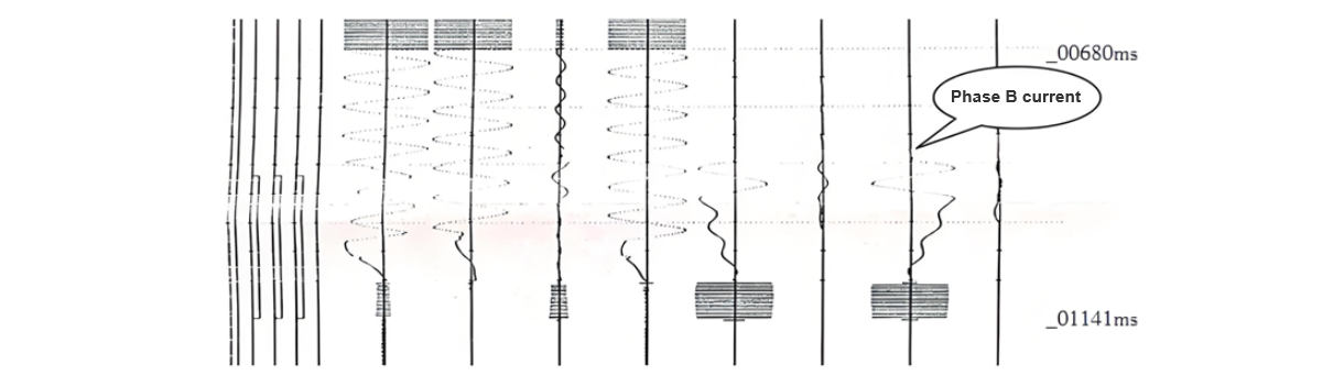
As can be seen from the reports of 7522, from 775 ms when the PRS - 721S protection device of the 7522 circuit breaker protection panel received the three - phase trip signal input from the IRC - 931BM protection device of the Jingchuan II line protection, to 925 ms when it tripped the local circuit breaker due to failure, and to 1025 ms when it tripped the adjacent circuit breaker due to failure, with a delay of 0.15 s for tripping the local circuit breaker and 0.25 s for tripping the adjacent circuit breaker respectively, which is in line with the operation logic of failure protection, and the protection operated correctly, as shown in Figure 3. In the oscillogram, it can be seen that although the B - phase tripping position contact of 7522 had returned at 825 ms, there was still current (arc) flowing between the moving and stationary contacts.
Conclusions
- Due to the severe distortion of the fault current, the waveform shifted to the lower side of the time - axis. The fact that the waveform did not cross zero within the effective arc - extinguishing time of the circuit breaker was the main reason for the non - extinction of the arc. The failure of the gap insulation to recover after the circuit breaker opened and the decline in the arc - extinguishing performance of SF₆ gas were secondary reasons for the non - extinction of the arc.
- The non - extinction of the arc and the expulsion of the remaining gas from the arc - extinguishing chamber, which carried out the arc, were the main reasons for the blackening of the insulating tie - rod and the outer wall of the capacitor.
- After the mechanical opening of phase B, the closing resistance was connected to the circuit. Since the arc between the breaks of phase B flowed through the closing resistance for 317 ms, the heat capacity caused the heat capacity of the connection between the closing resistance and the auxiliary break to break down, eventually leading to fusing, discharging to the outer - wall grading ring, resulting in the breakdown of the grading ring and the blackening of the resistance.
- The presence of arc current in phase B and its compliance with the operation logic of the circuit breaker failure protection were the main reasons for the tripping of the busbar.
Hey there! I'm an electrical engineer specializing in Failure and Maintenance. I've dedicated my career to ensuring the seamless operation of electrical systems. I excel at diagnosing complex electrical failures, from malfunctioning industrial motors to glitchy power distribution networks. Using state - of - the - art diagnostic tools and my in - depth knowledge, I pinpoint issues quickly. On this platform, I'm eager to share my insights, exchange ideas, and collaborate with fellow experts. Let's work together to enhance the reliability of electrical setups.