As a key component of circuit breakers, the insulating pull - rod is an important insulating and transmission part of Gas - Insulated Switchgear (GIS) equipment. It is required to have high reliability in terms of mechanical and electrical properties. Generally, insulating pull - rods rarely malfunction, but once a failure occurs, it can have serious consequences for the circuit breaker.
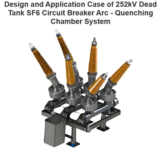
The 550kV circuit breaker in a certain power station has a single - break horizontal arrangement, with the model 550SR - K and a hydraulic operating mechanism. It has a breaking capacity of 63kA, a rated voltage of 550kV, a rated current of 4000A, a rated breaking current of 63kA, a rated lightning impulse withstand voltage of 1675kV, a rated switching impulse withstand voltage of 1300kV, and a rated power - frequency withstand voltage of 740kV. The insulating rod of the circuit breaker is made of epoxy resin, with a thickness of 15mm, a width of 40mm, and a density of 1.1 - 1.25g/cm³.
Fault Process
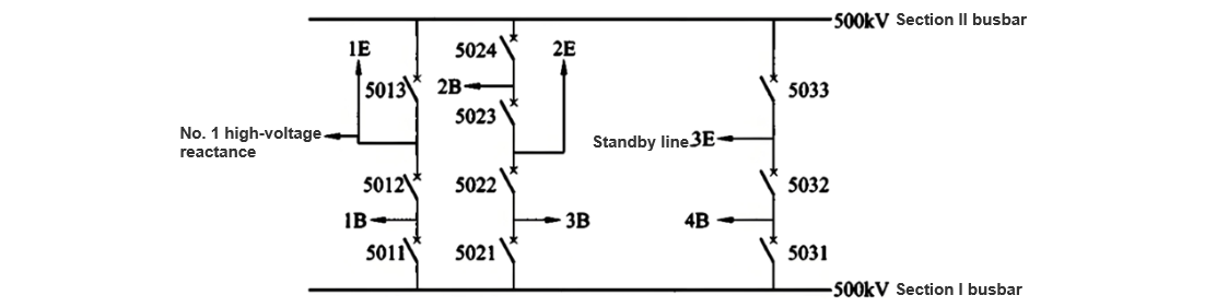
A certain hydropower station was preparing to resume power transmission for its No. 4 main transformer. The main electrical wiring of the power station is shown in Figure 1. The upper - level computer first opened the 5032 circuit breaker, and then opened the 5031 circuit breaker. The upper - level computer reported signals such as "TV Open - Circuit Alarm" and "5031 Circuit Breaker Protection Device Abnormality". On - site inspection revealed that both the protection device and the safety - control device of the 5031 circuit breaker had TV open - circuit alarms. The upper - level computer inspection found that for the voltage transformers in the T - zone of the 5032 and 5031 circuit breakers, Uab= 0, Uca = 306kV, and Ubc = 305kV. On - site actual inspection showed that both the 5032 and 5031 circuit breakers were in the open position.
Maintenance personnel measured the secondary winding voltage of phase C as 55V and that of phases A and B as 0V at the terminal box of the voltage transformer body in the T - zone of the 5032 and 5031 circuit breakers. It was initially judged that there was a fault in phase C of the 5031 circuit breaker.
On - site Inspection Situation
After the fault occurred, the power station immediately searched for the fault point on - site and carried out an analysis of the fault cause. It also contacted the provincial dispatching center to transfer the 5031 circuit breaker to the maintenance state. After the personnel from the circuit breaker manufacturer arrived at the site, they inspected the operating mechanism of the 5031 circuit breaker again. It was found that the position of the operating rod of the mechanism was in the normal "open" state, and no abnormality in the mechanism was detected, as shown in Figure 2. It was preliminarily determined that the fault was caused by an internal problem of the circuit breaker.

Considering that the closing resistance of the circuit breaker is far smaller than the grounding resistance, if the actual internal state of the circuit breaker is in the closed position, the grounding resistance of this circuit breaker will be significantly lower than that of the other two phases. The grounding resistances of the three - phase 5031 circuit breaker were measured without opening the grounding isolating switches on either side of the circuit breaker. The measurement results were as follows: Phase A was 273.3 μΩ, Phase B was 245.8 μΩ, and Phase C was 256.0 μΩ. No abnormal data was detected for Phase C.
After the 5031 circuit breaker was put into the maintenance state, the gas recovery process for the 5031C phase circuit breaker was initiated, and preparations were made for opening the cover for inspection. The upper flange of the 5031C phase circuit breaker was hoisted away. The inspection showed that the moving and static contacts of this circuit breaker were in the normal open position, the overall structure of the circuit breaker was intact, and no foreign objects or obvious discharge marks were found. Using a multimeter, the contact resistance between the moving and static contacts of the circuit breaker was measured to be 0.6 Ω (within the normal range), and there was no electrical connection between the moving and static contacts and the insulating pull - rod, as depicted in Figure 3.
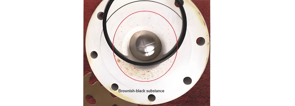
After lifting away the upper flange and the lower access hole of the circuit breaker again for inspection, a distinct burnt odor was detected in the gas chamber. There were brown - black powdery substances at the bottom of the gas chamber and at the location of the bottom explosion - proof membrane, as shown in Figure 4.
A manual slow - closing test was carried out on the 5031C - phase circuit breaker. The closing operation was normal, and no abnormal phenomena were observed. After the manual slow - closing was completed, the exterior of the circuit breaker body was inspected again. It was found that there were two discharge marks on the insulating pull - rod of the circuit breaker. One of them was obviously cracked, as shown in Figure 5. There were also tracking marks on the surface of the insulating pull - rod, and these marks extended across the entire insulating pull - rod.

After checking the insulating pull - rod and finding no new discharge points, a manual slow - opening test was conducted on the 5031C - phase circuit breaker. The opening operation was normal. After the opening was completed, the insulating pull - rod was inspected again, and still no new discharge points were found. A borescope was used to thoroughly inspect the interior of the circuit breaker, and no other abnormal phenomena were detected.
Fault Cause Analysis
After removing the faulty insulating pull - rod, it was observed and measured. The pull - rod was 570mm long, 40mm wide, and 15mm thick. There were two distinct discharge - burned spots on the entire insulating pull - rod, located 182mm and 315mm from the ends respectively. One of them had a crack approximately 53mm long. There were obvious traces of a tracking channel on the surface of the entire insulating pull - rod, which connected the inner - side holes at both ends of the pull - rod.
The insulation of the faulty insulating pull - rod was measured. When measured with a multimeter, the insulation between adjacent holes at the ends was normal. The insulation between the two inner - side holes at both ends was 1.583MΩ. When measured with an insulation resistance meter, the resistance value was 643kΩ (at a voltage of 1010V), and the insulation between the two outer - side holes at both ends was 1.52TΩ (at a voltage of 5259V). For a normal insulating pull - rod, the insulation between the two inner - side holes at both ends measured at a voltage of 5259V was greater than 5.26TΩ.
Based on the above inspection results, it can be determined that the insulation of the insulating pull - rod of the 5031C - phase circuit breaker had been punctured, and it showed conductivity under relatively low voltage conditions.
When the insulating pull - rod of the 5031C - phase circuit breaker was cut open for inspection, it was found that, except for the ends of the pull - rod where no air holes were visible, there were long air holes along the tracking channel inside the pull - rod, as shown in Figure 6.

Overall breakdown; second, the material proportioning or curing time of the insulating pull - rod did not meet the relevant requirements, resulting in uneven insulation strength of different parts of the insulating pull - rod. Under a strong electric field, the areas with lower insulation were first punctured, and then other low - insulation areas followed, ultimately leading to the overall breakdown of the insulating pull - rod .
Handling Measures
General Handling
After determining the fault cause of the 5031C - phase circuit breaker, the power station arranged for the replacement of the insulating pull - rod of the C - phase circuit breaker. After the replacement was completed, the gas chamber was evacuated, filled with gas to a rated pressure of 0.45MPa, and left to stand for 24 hours. Then, routine tests were carried out, including measuring the moisture content in the gas chamber, checking the closing resistance, conducting characteristic tests, and performing gas leak detection. After the routine tests passed, AC withstand voltage and partial discharge tests were conducted for the 5031 circuit breaker in both the open and closed states. The accessories were reinstalled, and an application for resuming power transmission was submitted.
AC Withstand Voltage and Partial Discharge Tests
The test voltage was applied from the spare line 3E. Before the test, the three - phase secondary circuits of all current transformers (TAs) on both sides of the 5031 circuit breaker and the 5032 circuit breaker were short - circuited and grounded at the main body. Also, the secondary circuits of all TAs on the spare line 3E were short - circuited and grounded at the main body, and the voltage transformers within the test range were removed. AC withstand voltage and partial discharge tests were respectively carried out when the 5031 circuit breaker was in the closed and open states.
For the 500kV GIS equipment in the power station, the highest operating voltage Um=550kV, the phase voltage Um/3=317kV, the factory test voltage Uc=740kV, and the maximum on - site withstand voltage Uf=Uc×80%=592kV, with a duration of t=60s .
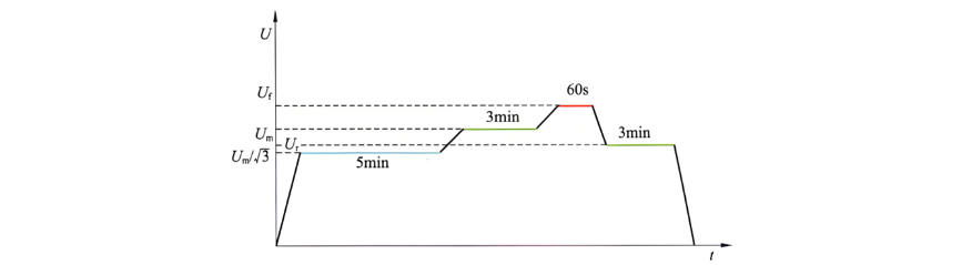
As shown in Figure7, the sequence of the closing withstand voltage and partial discharge tests is as follows: The GIS was aged and purified at a voltage of Um/3=317kV for 5 minutes, and the busbar was aged and purified at a voltage of U1=519kV for 3 minutes. The AC withstand voltage test was then increased to Uf=592kV and maintained for 60 seconds. The voltage was then rapidly reduced to Ur=381kV, and the partial discharge of the gas chamber of the 5031 circuit breaker was tested for 3 minutes. After the test, the voltage was rapidly reduced to 0kV.
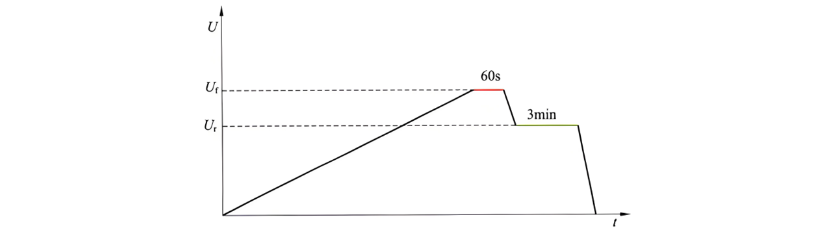
As shown in Figure 8, the test procedure for the open - circuit withstand voltage and partial discharge measurement is as follows: The test voltage was uniformly increased to Uf=592kV and maintained for 60 seconds. After the withstand voltage test was completed, the voltage was rapidly reduced to Ur=381kV, and the partial discharge of the gas chamber of the 5031 circuit breaker was tested. After the test, the voltage was rapidly reduced to 0kV.
Conclusion
The quality of the insulating pull - rods of 500kV SF₆ tank - type circuit breakers is of great significance for the safety of circuit breakers and the security of the power grid. Equipment manufacturers should exercise strict quality control. Before equipment assembly, partial discharge tests should be carried out on insulating pull - rods, and material inspections can be conducted using methods such as flaw detection if necessary. After the circuit breakers are put into operation, regular live partial discharge detection work should be carried out using methods like very high frequency and ultrasonic testing. At the same time, offline partial discharge live detection should be combined with circuit breaker maintenance. For circuit breakers with abnormal partial discharge levels, analysis of SF₆ gas decomposition products can be carried out simultaneously to diagnose the insulation health of SF₆ circuit breakers at an early stage, preventing equipment failures and ensuring the safe and stable operation of the power grid.