MMF Method of Voltage Regulation

The MMF Method, also referred to as the Ampere - Turn Method, operates on a principle distinct from the synchronous impedance method. While the synchronous impedance method relies on substituting the impact of armature reaction with an imaginary reactance, the MMF Method focuses on the Magnetomotive Force. Specifically, in the MMF Method, the effect of the armature leakage reactance is replaced by an equivalent additional armature reaction MMF. This allows for the combination of this equivalent MMF with the actual armature reaction MMF, facilitating a different approach to analyzing the electrical machine's behavior.
To calculate the voltage regulation using the MMF Method, the following pieces of information are essential:
- The resistance of the stator winding per phase.
- The open - circuit characteristics measured at synchronous speed.
- The short - circuit characteristics.
Steps to Draw the Phasor Diagram of the MMF Method
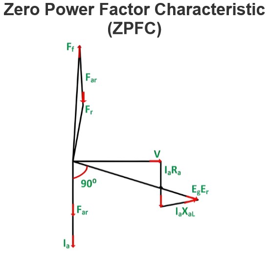
The phasor diagram corresponding to a lagging power factor is presented as follows:

Selecting the reference phasor:
The armature terminal voltage per phase, denoted as V, is chosen as the reference phasor and is represented along the line OA. This serves as the foundation for constructing the phasor diagram, providing a fixed point of reference for the other phasors.
Drawing the armature current phasor:
For the lagging power - factor angle ϕ for which the voltage regulation needs to be calculated, the armature current phasor Ia is drawn such that it lags behind the voltage phasor. This accurately reflects the phase relationship between the current and voltage in a lagging - power - factor electrical system.
Adding the armature resistance drop phasor:
The armature resistance drop phasor Ia Ra is then drawn. Since the voltage drop across a resistor is in phase with the current flowing through it, Ia Ra is drawn in phase with Ia along the line AC. After connecting points O and C, the line OC represents the electromotive force E’. This E’ is an intermediate quantity in the phasor - diagram construction, which helps in further analysis of the electrical machine's characteristics using the MMF method.

Based on the open - circuit characteristics depicted above, the field current If' corresponding to the voltage E' is computed.
Next, the field current If' is drawn such that it leads the voltage E' by 90 degrees. It is assumed that during a short - circuit condition, the entire excitation is counteracted by the magnetomotive force (MMF) of the armature reaction. This assumption is fundamental in the analysis, as it helps in understanding the interaction between the field and the armature under extreme electrical conditions.

With reference to the short - circuit characteristics (SSC) presented above, the field current If2 necessary to drive the rated current under short - circuit conditions is determined. This particular field current is what's needed to counterbalance the synchronous reactance drop Ia Xa.
Subsequently, the field current If2 is plotted in a direction that is exactly opposite to the phase of the armature current Ia. This graphical representation is crucial as it visually depicts the opposing magnetic effects between the field and the armature during a short - circuit event.

Calculating the Resultant Field Current
First, calculate the phasor sum of the field currents If' and If2. This combined value results in the resultant field current If. This If is the field current that would be responsible for generating the voltage E0 when the alternator is operating under no - load conditions.
Determining the Open - Circuit EMF
The open - circuit electromotive force E0, which corresponds to the field current If, can be obtained from the open - circuit characteristics of the alternator. These characteristics provide a relationship between the field current and the generated emf when the alternator has no load connected to it.
Calculating the Alternator's Regulation
The voltage regulation of the alternator can then be determined using the relation presented below. This regulation value is a crucial parameter as it indicates how well the alternator maintains its output voltage under varying load conditions.

This is all about MMF method of voltage regulation.