IEC and BS 7671 Requirements for Consumer Unit and Distribution Board
IEC-60364 and BS-7671 Guidelines for Garage Units, Consumer Units, and Distribution Boards
The International Electrotechnical Commission (IEC) and the British Standard BS 7671 play pivotal roles in shaping the requirements for electrical installations. Both sets of standards offer comprehensive guidance, particularly when it comes to fuse boards such as garage units, consumer units, and distribution boards.
IEC 60364 is a globally recognized standard that sets out international best practices for electrical installations. It provides a broad framework applicable across diverse regions, ensuring safety, reliability, and proper functionality. On the other hand, BS 7671 – 2018, which is harmonized with the IEC - aligned BS EN 61439, is specifically tailored to the United Kingdom. This standard builds upon the international principles while incorporating local regulations and considerations relevant to the UK electrical infrastructure.
The following sections delve into the key requirements stipulated by both IEC 60364 and BS 7671, focusing on the critical aspects related to electrical panels in various settings. These guidelines are essential for ensuring that electrical installations adhere to the highest safety and performance standards, safeguarding both property and individuals from electrical hazards.
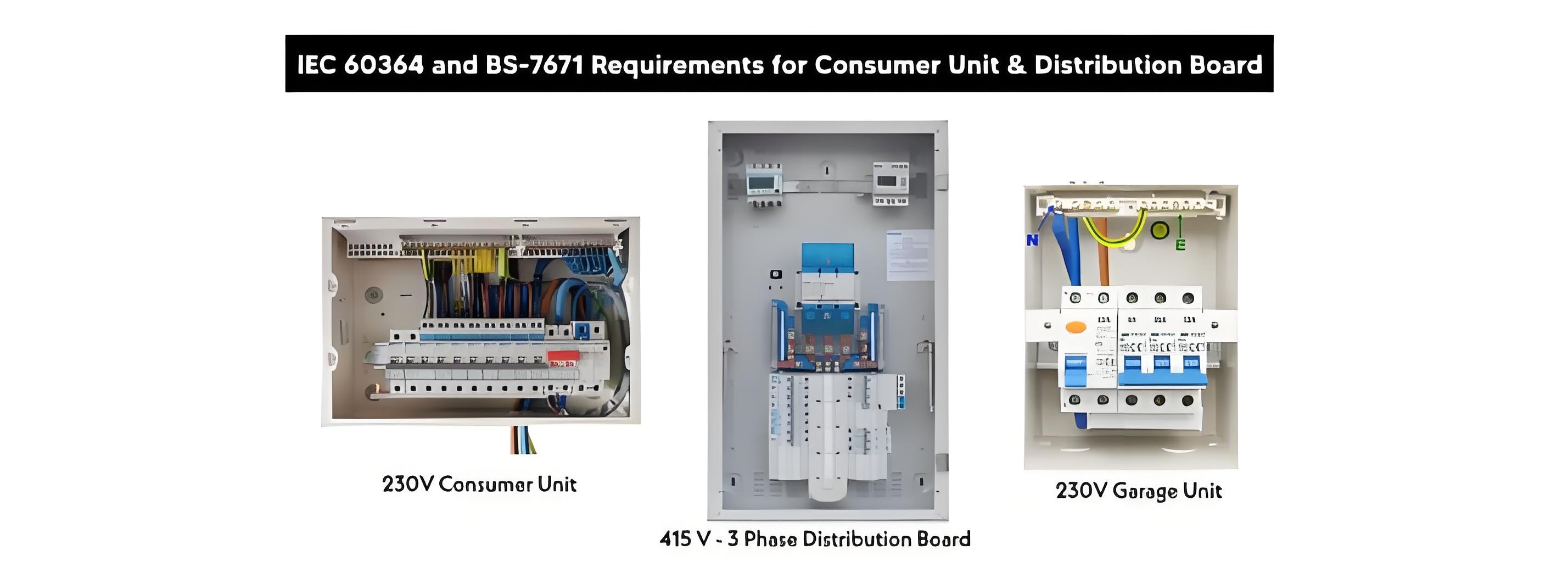
IEC-60364 and BS-7671 Guidelines for Garage Units, Consumer Units, and Distribution Boards
1. Location and Accessibility
As per BS 7671: 132.12 and IEC 60364 - 5 - 52:
Accessibility: Electrical panels must be situated in locations that are easily accessible for routine operation, maintenance, and inspections. This ensures that technicians can quickly and safely access the panels when needed.
Residential Settings: In residential environments, the recommended installation height for distribution boards and consumer units ranges from 1 to 1.8 meters above the floor. For the convenience of elderly individuals and those with disabilities, a height of 1.3 meters is suggested, facilitating easier interaction with the electrical panels.
Industrial Settings: In industrial buildings, for a typical distribution board with an IP54 degree of protection, the mounting area should have a maximum width of 1.50 meters, a maximum height of 1.20 meters, and a maximum depth of 0.50 meters, as specified in IEC 61439.
Clearance: Sufficient working space must be provided around electrical panels. BS 7671 emphasizes the importance of ensuring adequate room for safe access to all components, reducing the risk of accidents during operation or maintenance.
Switchgear Installation: Switchgear should generally be installed outdoors. However, it can be installed indoors if it is specifically designed for indoor use or enclosed in a cabinet with a protection degree of at least IP4X, IP5X, or IP6X, as per BS 7671: Section 422.3.3.
Double Insulation and Covers: When metallic distribution boards are installed, double insulation and covers must be used for live parts to prevent accidental contact and enhance safety.
Environmental Conditions: Electrical panels should be installed in areas free from water, excessive dust, and other adverse environmental factors that could compromise safety or performance. This helps to prolong the lifespan of the panels and ensures reliable operation.
2. Panel Ratings
In accordance with BS 7671: 536 and IEC 61439:
Component Selection: Distribution boards, consumer units, and related devices and equipment must be carefully selected based on their current - carrying capacity and the overall load requirements of the electrical system. This ensures that the panels can handle the electrical demands without overheating or failing.
Design and Testing Standards: IEC 61439 governs the design, testing, and construction of electrical panels (low - voltage switchgear and controlgear assemblies). These standards ensure that panels meet strict safety and performance requirements, providing reliable protection for electrical systems.
Protective Device Verification: All protective devices used in residential consumer units and commercial/industrial distribution boards must be verified in accordance with BS EN 61439 - 3 and comply with IEC - 60898 and IEC 60947 - 2 for B, C, and D curves. This verification process ensures that the protective devices will operate correctly in the event of a fault.
Environmental Suitability: Panel boards must be suitable for the intended environment, taking into account insulation and temperature ratings. This ensures that the panels can withstand the specific conditions of their installation location, such as temperature fluctuations and humidity.
3. Isolation and Switching
As stipulated by BS 7671: Section 537 and IEC 60364 - 5 - 53:
Isolation and Switching Provisions: Electrical panels must be equipped with adequate means for isolation and switching. This allows circuits to be safely disconnected during maintenance activities or in case of emergencies, preventing electrical shocks and damage to equipment.
Main Isolator Requirements: Main isolators should be clearly labeled and easily accessible. In situations where isolation is necessary for safety, the isolator must be capable of disconnecting all live conductors (phase and neutral) simultaneously.
Emergency Disconnect: An interrupting device or emergency disconnect switch must be installed to enable the main power supply to be quickly disconnected in the event of an emergency or danger. This ensures that immediate action can be taken to protect personnel and equipment, as required by BS 7671: Sections 132.9 and 132.10.
4. Earthing and Protective Conductors
According to BS 7671: Chapter 54 Sections 541 to 544 and IEC 60364 - 5 - 54:
Earthing Importance: Proper earthing (grounding) is essential for protecting users and equipment from electric shock. It provides a safe pathway for fault currents to dissipate into the ground, reducing the risk of electrical accidents.
Protective Earth Connections: Electrical panels must be equipped with reliable protective earth connections. Proper bonding ensures that exposed conductive parts do not pose a safety risk by equalizing electrical potential and preventing dangerous voltage differences.
Equipotential Bonding: Equipotential bonding should be implemented to prevent the development of dangerous voltages between exposed metalwork. This helps to create a safe electrical environment by ensuring that all metal parts are at the same electrical potential.
Lightning Protection Compliance: As per BS 7671: 541.3, if a lighting protection system is present, the installation should comply with the reference standards in BS EN 62305 to ensure effective protection against lightning - related electrical surges.
PEN Conductor Restrictions: In hospitals, emergency units, and other medical locations downstream of the main distribution board or consumer unit, PEN conductors shall not be used, as specified in BS 7671 - 2028: 710.312.2. This restriction is in place to enhance electrical safety in these critical healthcare environments.
5. Selection of Protective Devices
In line with BS 7671: 536.3 and IEC 60364 - 5 - 53:
Fault Coordination: Protective devices within the electrical panel should be carefully coordinated. This ensures that in the event of a fault, only the affected circuit is disconnected, rather than the entire system. Proper coordination is crucial for maintaining the safety and reliability of electrical installations, especially in complex multi - circuit systems.
6. Overcurrent Protection
As per BS 7671: Chapter 43, Sections 420 to 424 and IEC 60364 - 4 - 43:
Overcurrent Protection Devices: Electrical panels must be equipped with appropriate overcurrent protection devices (OCPDs), such as fuses, miniature circuit breakers (MCBs), residual current devices (RCDs), residual current breakers with overload protection (RCBOs), arc - fault detection devices (AFDDs), and surge protection devices (SPDs).
Rating and Design: The OCPDs should be rated based on the design of the electrical circuit to prevent damage to wiring and reduce the risk of electrical fires. Properly rated OCPDs will trip when excessive current flows, protecting the electrical system from overheating and potential hazards.
Coordination Requirements: BS 7671 mandates proper coordination between conductors, OCPDs, and other protective devices. This ensures that conductors are protected against thermal damage, maintaining the integrity of the electrical installation.
7. Short Circuit Protection
In accordance with BS 7671: 434 and IEC 60364 - 4 - 43:
Short Circuit Protection Provision: Electrical panels must be equipped with protection against short circuits. The protective devices should be rated to interrupt the maximum fault current that could occur in the system. This ensures that short circuits are quickly cleared, minimizing damage to equipment and reducing the risk of electrical fires.
Device Selection and Operation: Short circuit protection devices should be selected based on the expected fault current levels and should operate rapidly to isolate the fault. Quick - acting short circuit protection is essential for maintaining the safety and reliability of electrical systems.
8. RCDs, AFDDs, and Earth Fault Protection
As per BS 7671: 415, 536, and IEC 60364 - 4 - 41:
Residual Current Devices (RCDs): RCDs are required to provide additional protection against electric shock, particularly in circuits supplying socket outlets and equipment in wet or outdoor locations. They quickly detect and interrupt any imbalance in current flow, which can indicate a leakage current or a person coming into contact with a live conductor.
30mA High - Sensitivity RCDs: A 30mA high - sensitivity RCD must be installed in the consumer unit for socket - outlet circuits, circuits feeding bathrooms, and lighting circuits, as per IEC 60364. This level of sensitivity provides enhanced protection against electric shock hazards.
TT System Requirements: In a TT system where RCD protection is not present, double or reinforced insulation must be provided on all circuits upstream of the first RCD to ensure the safety of the operator. This alternative measure helps to prevent electric shock in the absence of RCD - based protection.
Earth Fault Protection: Earth fault protection must be in place to disconnect the power supply in the event of a fault that could lead to electrocution or equipment damage. This protection mechanism ensures that the electrical system is safely isolated when a fault occurs.
TN System Requirements: In a TN system, earth fault protection should be provided via a circuit breaker. The protective earth conductor (PE) and the exposed conductive parts of all insulated appliances and equipment must be connected to the consumer - installed earth electrode. This connection ensures that fault currents are safely diverted to the ground, protecting users and equipment.
9. Environmental Protection (IP Ratings)
According to BS 7671: 512.2 and IEC 60364 - 5 - 52:
IP Rating Selection: Electrical panels must have appropriate Ingress Protection (IP) ratings based on their installation environment. Whether installed indoors, outdoors, in dusty, or wet areas, the IP rating ensures that the panel enclosure provides adequate protection against the ingress of solid objects and liquids, safeguarding the internal components from damage.
Temperature Limits: Electrical equipment should be installed in a manner that ensures the design temperature does not exceed the specified limits, as per BS 7671: Section 134.1.5. This prevents overheating, which can lead to component failure and potential safety hazards.
10. Segregation of Circuits
As per BS 7671: 514.10 and IEC 60364 - 5 - 52:
Circuit Segregation: Different types of circuits, such as power, lighting, and control circuits, must be segregated within the electrical panel. This segregation helps to prevent interference between circuits and reduces the risk of faults spreading from one circuit to another.
Voltage Rating Separation: Cables and components with different voltage ratings should not be installed in the same compartment without adequate insulation or separation. This ensures that there is no electrical interaction between components with different voltage requirements, maintaining the safety and integrity of the electrical system.
11. Cables Used in Wiring Systems
According to BS 7671: Section 422.3.4:
Material and System Standards:
Cables made from non - combustible materials must comply with EN 60332 - 1 - 2.
Conduit systems should adhere to BS - EN 61386 - 1.
Cable trunking and ducting systems must meet the requirements of BS - EN 50085.
Cable tray or ladder systems should comply with BS - EN 61537.
Power track systems must satisfy the flame propagation resistance requirements specified in BS - EN 61534.
Wiring systems with a high risk of flame propagation must meet the requirements of BS - EN 60332 - 3. These standards ensure the safety and reliability of the wiring system, minimizing the risk of electrical fires and other hazards.
12. Circuit Identification and Labeling
In accordance with BS 7671: 514.1 and IEC 60364 - 5 - 51:
Circuit Labeling: All circuits within the electrical panel must be clearly labeled to indicate their function and the areas they serve. A suitable indicator that complies with BS EN 60073 and BS EN 60447 should be positioned in a location that is clearly visible to the operator. This clear labeling helps technicians quickly identify and troubleshoot circuits during maintenance or repairs.
Protective Conductor Information: Information indicating the high - current protective conductor should be provided and be clearly visible to anyone working on or modifying the circuit, as per BS 7671 - 2028: 543.7.1.205. This information is crucial for ensuring proper installation and maintenance of the protective grounding system.
Diagram Provision: A single - line diagram, drawing, or general schematic diagram containing the full details of all electrical safety sources should be placed adjacent to the distribution board or consumer unit, as required by BS 7671 - 2028: 560.7.9 and 560.7.10. This diagram provides a comprehensive overview of the electrical system, aiding in understanding and troubleshooting.
Color Coding: The color coding of conductors should conform to established standards to ensure clarity for electricians and maintenance personnel. In BS 7671, the phase (live) conductor is brown, the neutral is blue, and the protective earth is green/yellow. However, some countries following British standards and IEC, including the UK prior to 2004, used red, black, and green for phase, neutral, and earthing conductors, respectively. For accurate color coding in AC and DC systems, it is essential to refer to the relevant IEC and NEC wiring color codes.
13. Verification and Testing
As per BS 7671: Part 6 and IEC 60364 - 6:
Post - Installation Inspection: After installation, electrical panels must undergo a thorough inspection and testing process to verify compliance with BS 7671 and IEC standards. This inspection ensures that all components are installed correctly and that the panel functions as intended.
Functionality Testing: The testing process should confirm the proper functionality of protective devices, correct wiring, and proper earthing. This includes checking that circuit breakers trip at the correct current levels, RCDs detect and interrupt leakage currents, and that the grounding system provides effective protection.
Periodic Inspections: Periodic inspections and testing are also required to ensure the ongoing safety of electrical installations. Regular checks help to identify any potential issues or deterioration over time, allowing for timely maintenance and repairs to prevent electrical accidents.
In conclusion, both IEC 60364 and BS 7671 play a vital role in ensuring the safety, reliability, and efficiency of electrical systems. Adhering to these comprehensive standards helps to prevent electrical fires, protect against electric shock hazards, and safeguard electrical equipment from damage, providing peace of mind for both installers and end - users.
The Electricity Encyclopedia is dedicated to accelerating the dissemination and application of electricity knowledge and adding impetus to the development and innovation of the electricity industry.

