Search
Italiano
English
Español
Français
العربية
Русский
Português
हिन्दी
বাংলা
Deutsch
日本語
Bahasa Indonesia
Italiano
RFQ
Home
Market
Solutions
Knowledge
Download the app
MENU
Home
Market
Solutions
Knowledge
Italiano
English
Español
Français
العربية
Русский
Português
हिन्दी
বাংলা
Deutsch
日本語
Bahasa Indonesia
Italiano
Home
Knowledge
Voltage Multiplier
Topics
Power Systems
Power system
Machines
circuit diagram
Measurement
Basic Electrical
Basic
Industrial circuit
Basic knowledge
Transmission
Electric Power Knowledge
Control
Motor
Transformer
Electric Motors
Protection
household circuit
Generation
Control Circuit
Switchgear
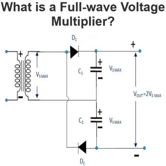
What is a Full-wave Voltage Multiplier?
What is a Full-wave Voltage Multiplier?Full wave voltage multiplier definitionCharge the capacitor during positive and negative cycles, providing double voltage output and better high-frequency ripple filtering.Input waveformOutput waveform
Encyclopedia
07/16/2024
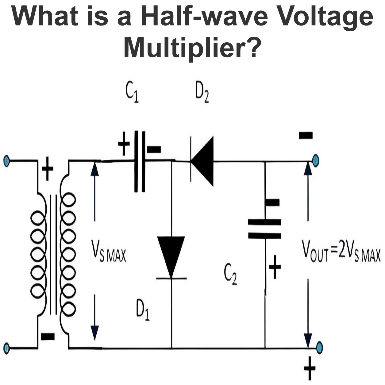
What is a Half-wave Voltage Multiplier?
What is a Half-wave Voltage Multiplier?Half wave voltage multiplier definitionThe capacitor is alternately charged during positive and negative cycles, resulting in an output twice the peak input voltage.Input waveformOutput waveform
Encyclopedia
07/16/2024
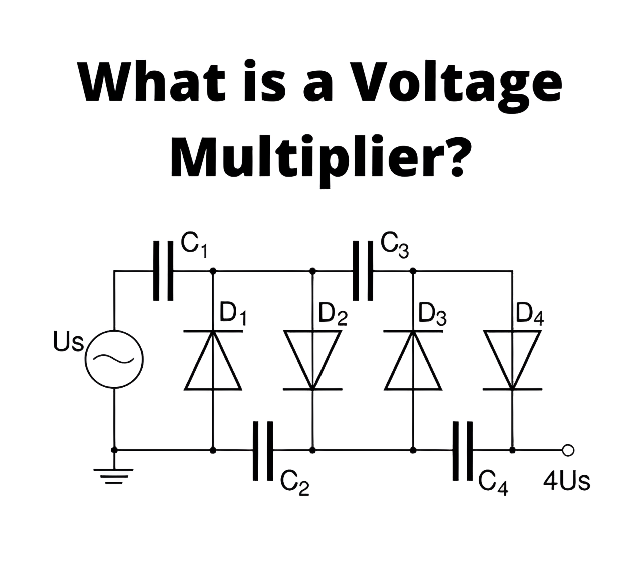
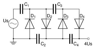
What is a Voltage Multiplier?
What is a Voltage Multiplier?Voltage Multiplier definitionA voltage multiplier is a circuit that produces a DC voltage that is much higher than the peak AC input voltage by using capacitors and diodes.How the Voltage Multiplier works Using the energy storage characteristics of capacitors and the unidirectional conductivity of diodes, the voltage multiplication process is as follows: First, the input AC power is passed through a rectifier, usually rectified using a diode or a rectifier bridge, co
Encyclopedia
07/16/2024
Voltage Multiplier
It is in actuality a modified capacitor filter circuit (rectifier circuit) which makes a DC output voltage that is two or more than two times the AC peak input. In this section, we can look into full-wave voltage doubler, half-wave voltage doubler, voltage tripler and finally quadrupler.Half Wave Voltage DoublerThe input wave form, circuit diagram and output waveform is shown in figure 1. Here, all through the positive half cycle, the forward biased D1 diode conducts and diode D2 will be in off
Electrical4u
03/11/2024
Source professional electrical partners, experts, and explore smart grid & energy solutions.
Inquiry
Send Now
Download
Experts Electrical is dedicated to serving the personnel in the global power industry.
Join Experts Electrical, not only can you discover power equipment and power knowledge, but also canhnd like - minded friends!