Search
Русский
English
Español
Français
العربية
Русский
Português
हिन्दी
বাংলা
Deutsch
日本語
Bahasa Indonesia
Italiano
RFQ
Home
Market
Solutions
Knowledge
Download the app
MENU
Home
Market
Solutions
Knowledge
Русский
English
Español
Français
العربية
Русский
Português
हिन्दी
বাংলা
Deutsch
日本語
Bahasa Indonesia
Italiano
Home
Knowledge
Synchronous Generator
Topics
Power Systems
Power system
Machines
circuit diagram
Measurement
Basic Electrical
Basic
Industrial circuit
Basic knowledge
Transmission
Electric Power Knowledge
Control
Motor
Transformer
Electric Motors
Protection
household circuit
Generation
Control Circuit
Switchgear
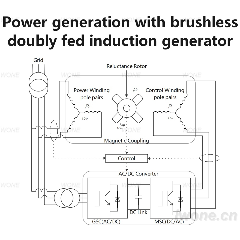
Power generation with brushless doubly fed induction generator
Power generation with brushless doubly fed induction generator
Master Electrician
09/05/2024
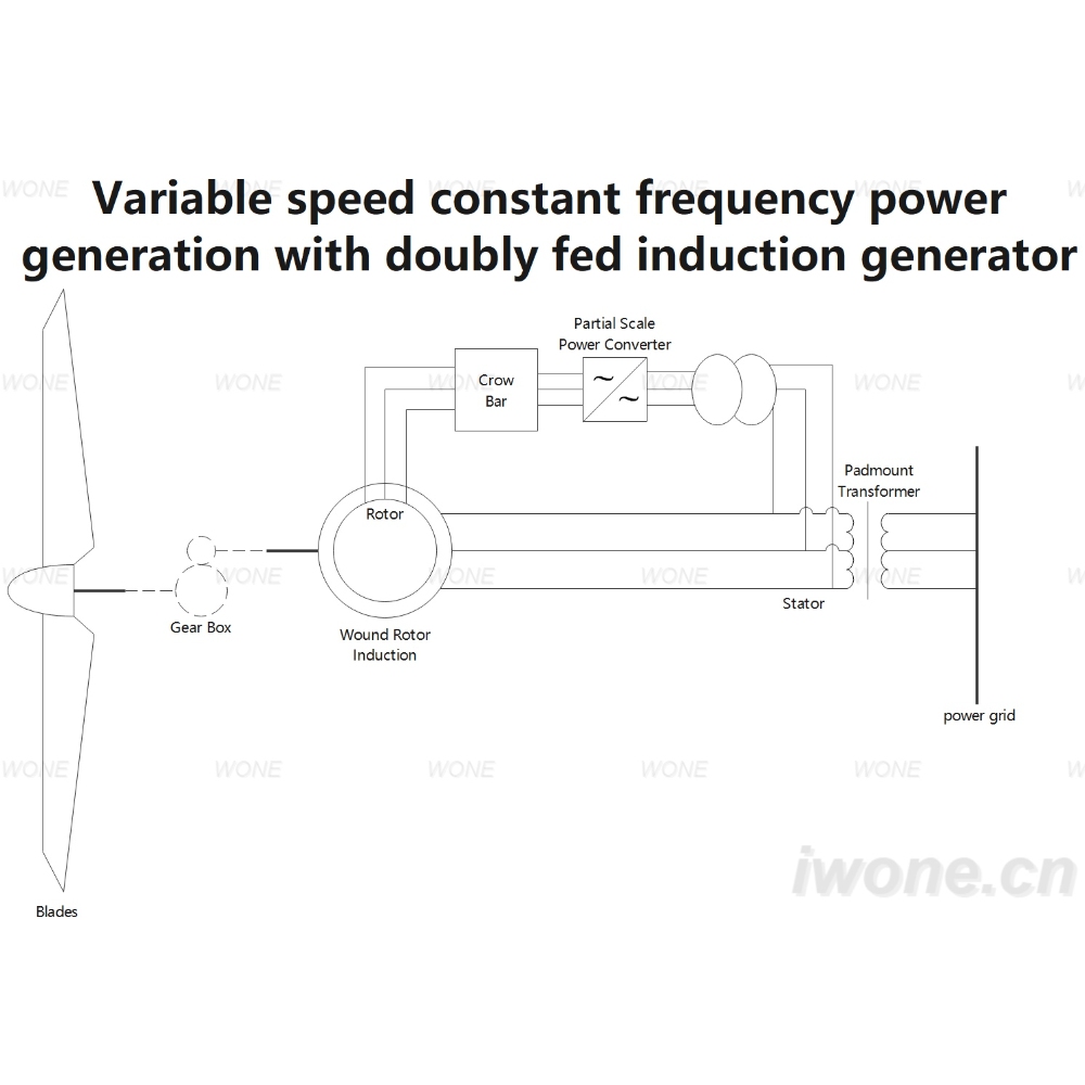
Variable speed constant frequency power generation with doubly fed induction generator
Variable speed constant frequency power generation with doubly fed induction generator
Master Electrician
09/05/2024
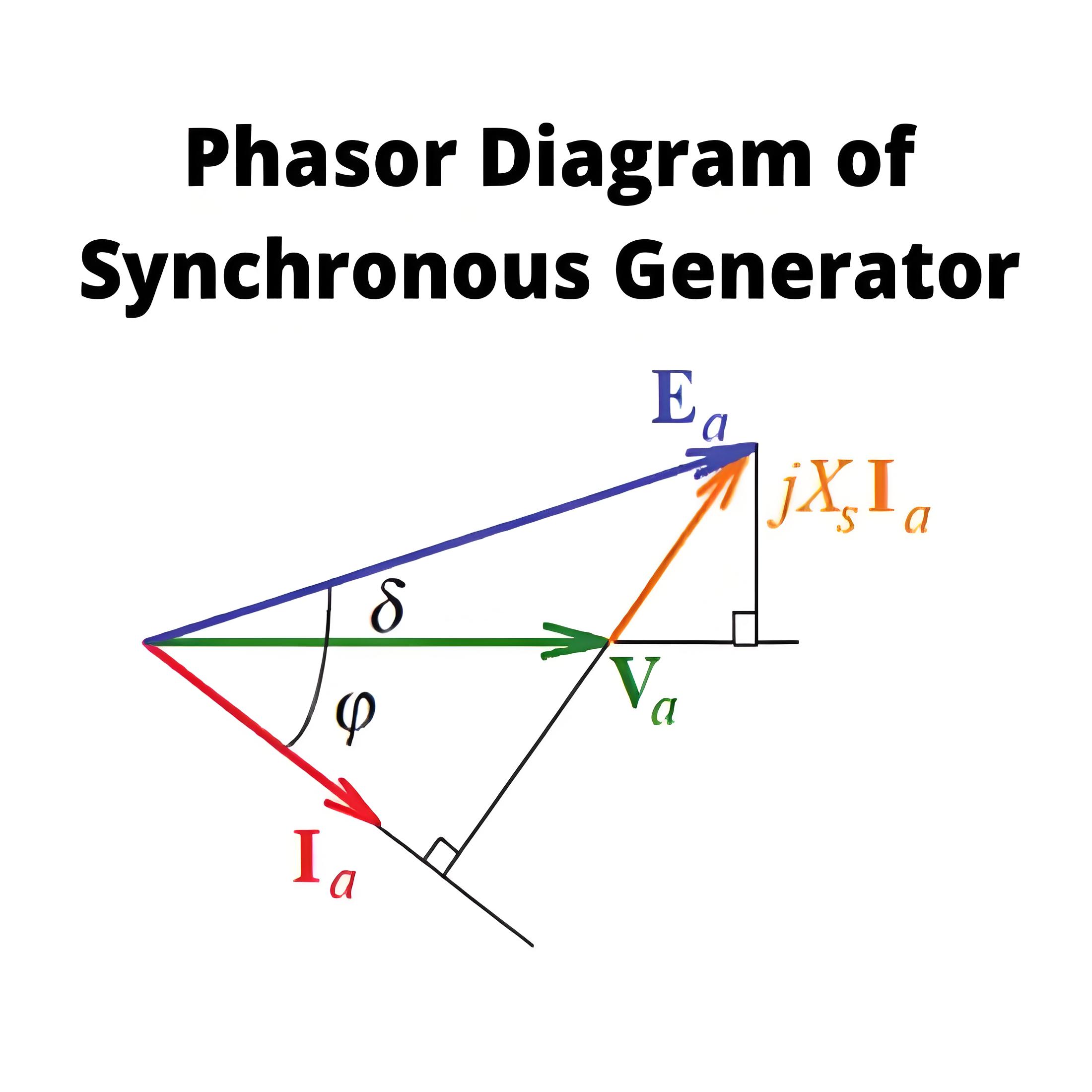
Phasor Diagram of Synchronous Generator
Phasor Diagram DefinedA phasor diagram is a graphical representation of the phase relationships between different electrical quantities in an AC circuit, specifically used here for synchronous generators.Drawing BasicsEf which denotes excitation voltageVt which denotes terminal voltageIa which denotes the armature currentθ which denotes the phase angle between Vt and Iaᴪ which denotes the angle between the Ef and Iaδ which denotes the angle between the Ef and Vtra which denotes the armature per
Encyclopedia
08/19/2024
Source professional electrical partners, experts, and explore smart grid & energy solutions.
Inquiry
Send Now
Download
Experts Electrical is dedicated to serving the personnel in the global power industry.
Join Experts Electrical, not only can you discover power equipment and power knowledge, but also canhnd like - minded friends!