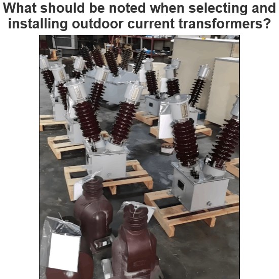
How does an inverter perform Pulse Width Modulation (PMW)?
The core concept of PWM (Pulse Width Modulation) is to control the average output voltage by changing the pulse width of the signal. Here are the detailed steps:
Reference Signal (Carrier Signal): PWM inverters typically use a fixed frequency triangular wave (or sawtooth wave) as a reference signal, known as the carrier signal.
Modulation Signal: The modulation signal is a varying sine wave that represents the desired output AC waveform. The amplitude of the modulation signal determines the magnitude of the output voltage, while its frequency determines the frequency of the output voltage.
Comparison: The modulation signal is compared with the carrier signal. When the instantaneous value of the modulation signal is greater than that of the carrier signal, a high-level output is produced; otherwise, a low-level output is produced.
Generation of PWM Waveform: Through the above comparison process, a series of rectangular waves with varying widths are generated. The width of these rectangular waves changes over time, simulating the shape of a sine wave.
Filtering: Finally, a filter is used to remove the high-frequency components from the PWM waveform, resulting in a smoother sine wave output.