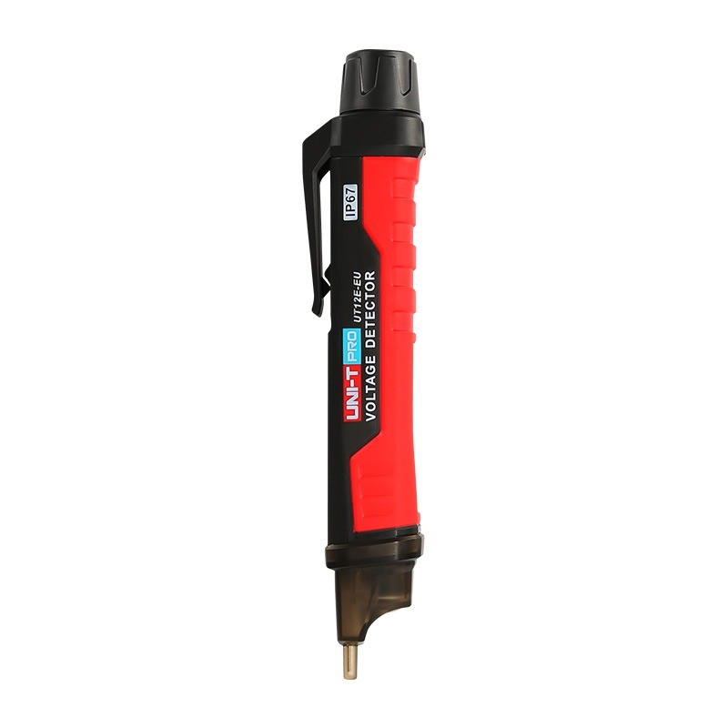
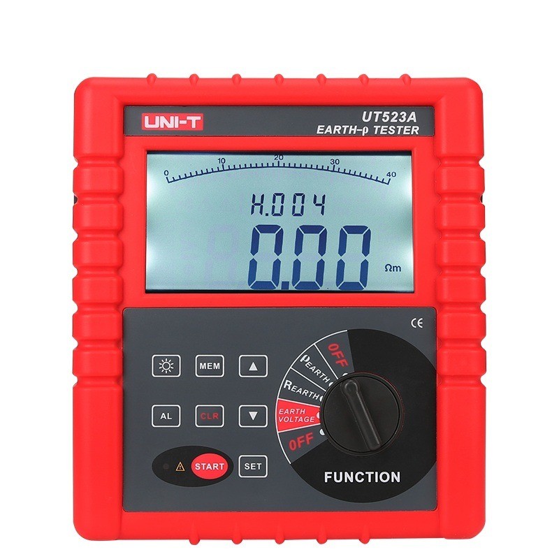
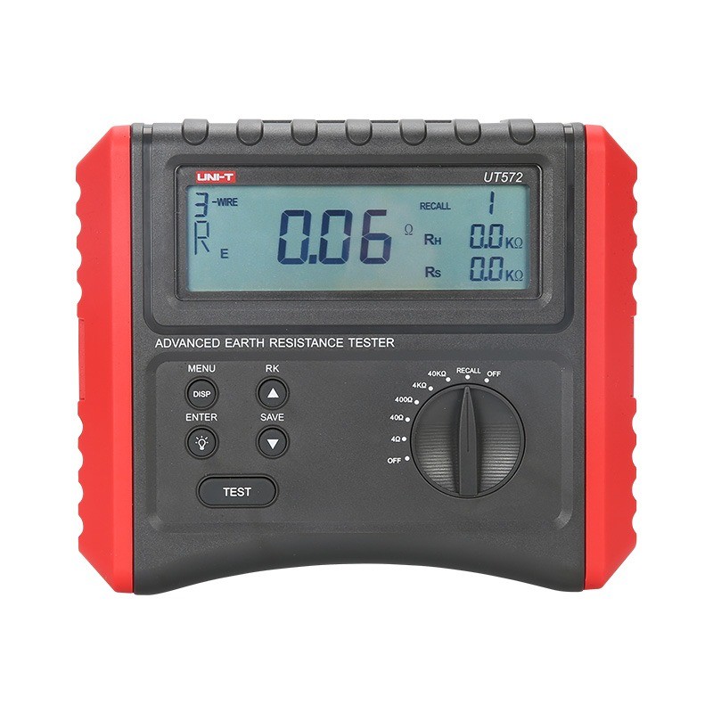
• Wire Tracer for Underground and Wall Electrical Wires and Pipes
  • Wire Tracer for Underground and Wall Electrical Wires and Pipes
  • Wire Tracer for Underground and Wall Electrical Wires and Pipes
  • Wire Tracer for Underground and Wall Electrical Wires and Pipes
Wire Tracer for Underground and Wall Electrical Wires and Pipes
$150.00
Model
NF826
Basic info
Brand Wone
Model NO. NF-826 Wire Tracer for Underground and Wall Electrical Wires and Pipes
Max Depth Range 1000m
Max Cable Length 2m (80 inch)
Series NF
Product Detail

Features

  • Circuit Tracer: Trace circuits and find electrical wires and metal (copper, network, power) cables in drywall or underground. The Max detection range is 2m (80in).

  • Wiring Fault Locator: Tone locating faults like breaks, open circuits, and short circuits in wires and cables. Flexible scanning strength for various environments.

  • Breaker Finder: Attach the transmitter device to a socket via adapters. Locate socket breakers on the box with one tap.

  • Voltmeter: The transmitter has an integrated AC / DC voltmeter for linear measurement of 12-400V DC/AC voltage.

  • Electricity Detector: The receiver (the tone probe) can detect AC voltage over 60V without touching the object.

  • Pipe Locator: Detect the wiring and direction of underground water, heating, and gas pipelines without breaking the lawn and floor. Locate the breakpoints in the pipe easily.

  • A Built-in LED Light: An internal LED light illuminates the dark environment for easy operation.

  • Certification: Passes RoHS, FCC, and CE compliance testing.

  • Fair Price: Compared to expensive Klein and Fluke wire tracers,  NF-826 is a lot more friendly to your budget.

  • Versatile Accessories for Precision: Provide a comprehensive set of accessories tailored for diverse scenarios, ensuring your wire tracing needs are met with precision and efficiency. Elevate your experience with our all-in-one solution for seamless connectivity troubleshooting.

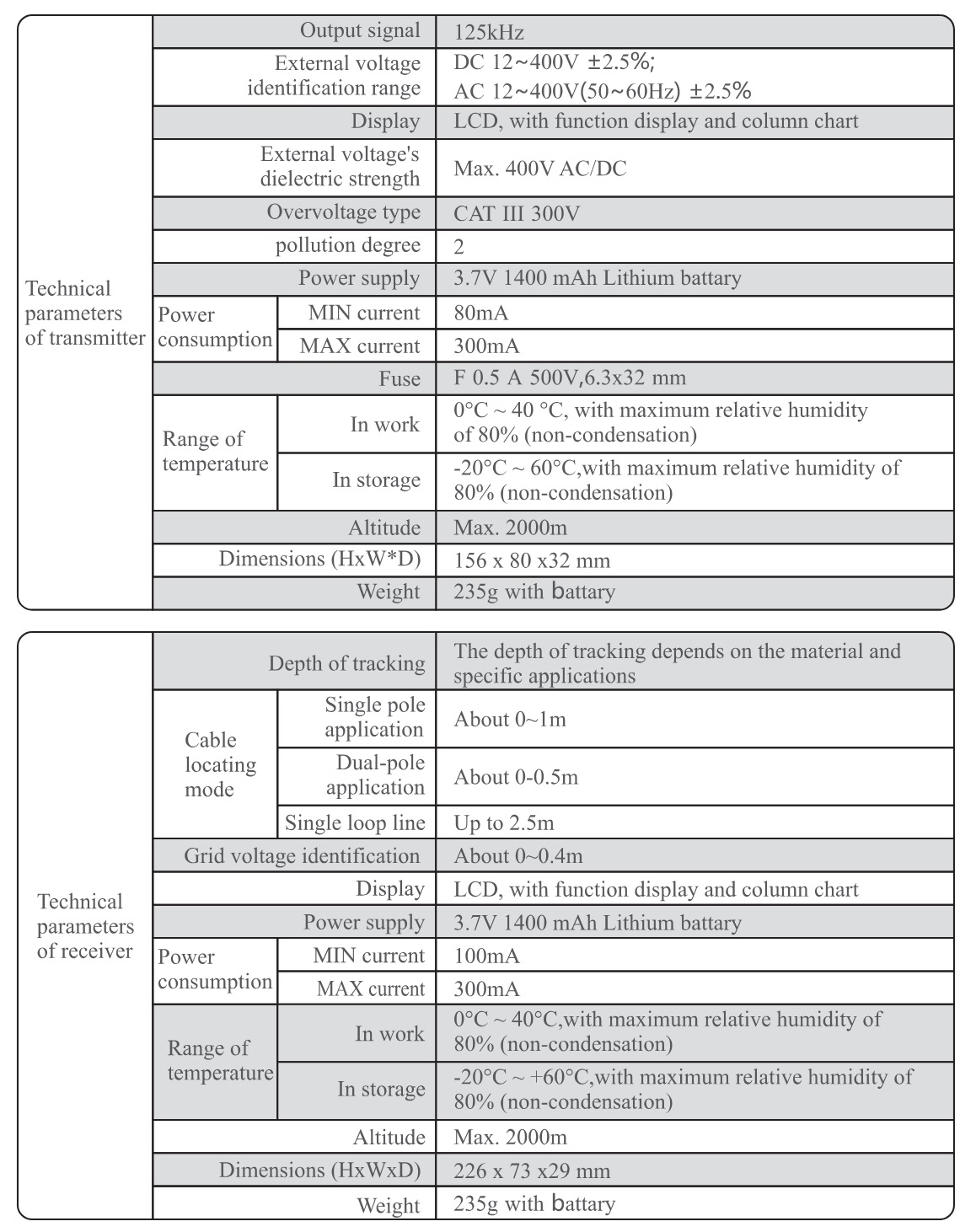
Techical parameters
1718692959495.jpg

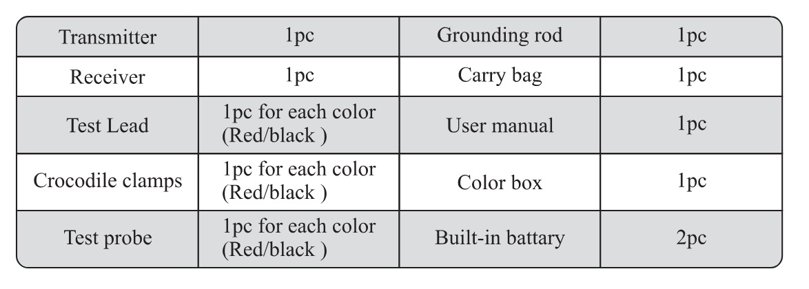
Accessories

1718692985085.jpg

How is the transmitter inductively coupled in a wire tracker?

Inductive Coupling

Inductive coupling is a method of transmitting signals to a target wire through electromagnetic induction without the need for direct contact with the wire. Instead, the signal is transmitted via the alternating magnetic field generated by the transmitter. Here's the process:Generation of Alternating Magnetic Field by the Transmitter:

The transmitter contains a coil that produces an alternating current when the transmitter is active. This alternating current creates a varying magnetic field around the transmitter.

Induction of Current in the Target WireWhen the varying magnetic field passes through the target wire, an induced electromotive force (EMF) is generated within the wire according to Faraday's law of electromagnetic induction. This induced EMF causes an induced current to flow in the wire, thereby impressing the signal generated by the transmitter onto the wire.


Know your supplier
Wone
Main Categories
High voltage/Low voltage/Wire cable/Instrument meters/New energy/Tester/Production equipment/Generator/Electrical fittings/Integrated Electrical Equipment
Business Type
Design/Manufacture/Sales
Highest Annual Export (USD)
$50,000,000
Professional Experience
1 years
Workplace
65666m²m²
占位
占位
Related Products
Related Knowledges
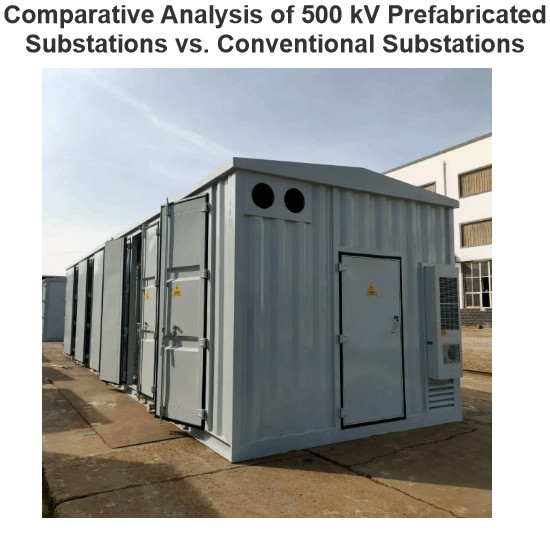
Comparative Analysis of 500 kV Prefabricated Substations vs. Conventional Substations
The secondary equipment area of conventional substations uses reinforced concrete or prefabricated steel structures, facing issues like long construction cycles, unreasonable functional zone design, strict environmental assessments, dust, noise, and disturbances. Primary and secondary equipment can only be installed after civil works and decoration, lowering construction efficiency.Prefabricated cabin substations integrate modularity, intelligence, and cost - effectiveness, boasting green, energ
Dyson
06/13/2025
Operational Analysis of Prefabricated Enclosure Substations in Extreme Cold Climate Applications
Under global climate diversity, alpine power construction faces technical and environmental challenges. Extreme climates, complex geology, and long - term low winter temperatures, along with ice, snow, and storms, strain electrical equipment stability and power facility construction (schedule, cost, maintenance). Traditional on - site substations, with long construction and poor adaptability, can’t meet alpine regions’ fast, stable power needs.Prefabricated cabin substations, as modu
Echo
06/13/2025
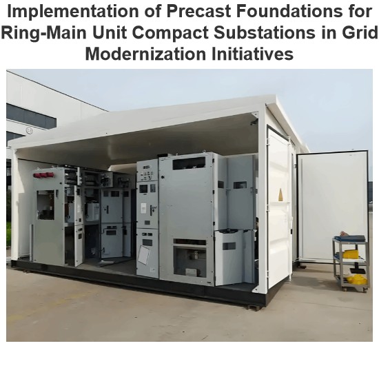
Implementation of Precast Foundations for Ring-Main Unit Compact Substations in Grid Modernization Initiatives
Compact substation boxes, with advantages like safe operation, high reliability, and easy maintenance, are used in urban grid construction/renovation. Structurally divided into American - style (high - cost, noisy, low - efficiency, gradually phased out) and European - style (large - sized but more advantages, still popular).To address their pros/cons, ring - network prefabricated ones were developed.I. Basic Materials for Prefabricated Compact Substation BoxesMaterials need hardness, strength,
Echo
06/13/2025
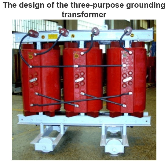
The design of the three-purpose grounding transformer
Underground Power Cable Transmission LinesDirect - buried power cable lines have large ground - distributed capacitance, causing high single - phase - to - ground short - circuit capacitive current. For 10 kV lines, if this current exceeds 10 A, arcs hardly self - extinguish, risking arc overvoltage and endangering line equipment. Arc extinction is thus necessary. With a Dyn - connected main transformer, an arc - suppression coil on the secondary neutral point suffices. For Yd - connected ones,
Dyson
06/12/2025
Failure Analysis and Design Optimization of Conventional Grounding Transformers
I. Core Cause of Damage: Electrodynamic Impact (Complying with GB/T 1094.5 / IEC 60076-5)The direct cause of high-voltage winding end collapse is the instantaneous electrodynamic impact induced by short-circuit current. When a single-phase grounding fault occurs in the system (such as lightning overvoltage, insulation breakdown, etc.), the grounding transformer, as the fault current path, withstands high-amplitude and steep-rise-rate short-circuit currents. According to Ampère's force law
Felix Spark
06/12/2025
Analysis of Grounding Transformer Operational Behavior Under System Single-Phase-to-Ground Fault Conditions
1 Theoretical AnalysisIn distribution networks, grounding transformers serve two key roles: powering low - voltage loads and connecting arc - suppression coils at neutrals for grounding protection. Grounding faults, the most common distribution network fault, heavily impact transformers’ operating characteristics, causing sharp changes in electromagnetic parameters and status.To study transformers’ dynamic behaviors under single - phase grounding faults, build this model: Assume a tr
Felix Spark
06/12/2025
×
Inquiry
Download
Experts Electrical is dedicated to serving the personnel in the global power industry.
Join Experts Electrical, not only can you discover power equipment and power knowledge, but also canhnd like - minded friends!
商品视频播放