The secondary equipment area of conventional substations uses reinforced concrete or prefabricated steel structures, facing issues like long construction cycles, unreasonable functional zone design, strict environmental assessments, dust, noise, and disturbances. Primary and secondary equipment can only be installed after civil works and decoration, lowering construction efficiency.
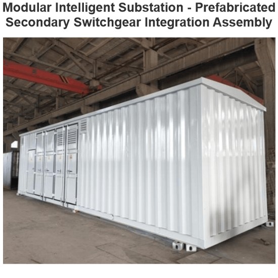
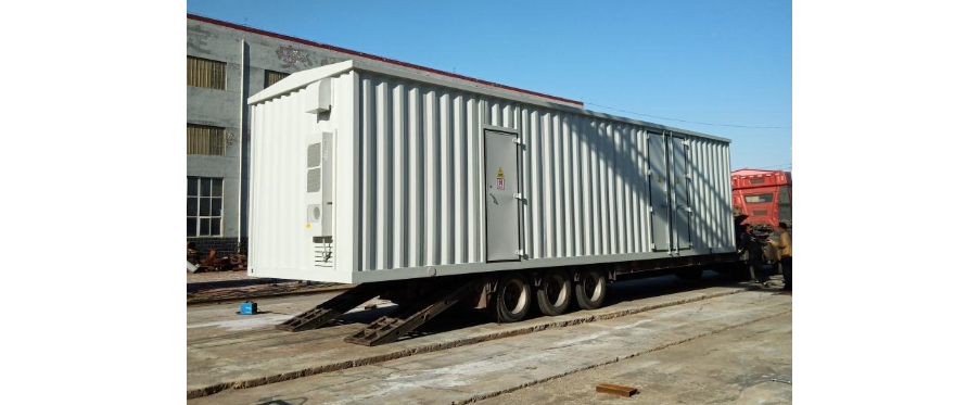
Prefabricated cabin substations integrate modularity, intelligence, and cost - effectiveness, boasting green, energy - saving, and efficient advantages. They address conventional substation problems such as high costs, long timelines, difficult maintenance, excessive workloads, and poor quality.
The 500 kV prefabricated cabin substation’s enclosure uses new vacuum insulation panels and phase - change energy - storage materials. These materials ensure reliable equipment operation while reducing energy consumption. This paper studies the prefabricated cabin’s layout, waterproofing, HVAC, and fire - protection systems, comparing them with conventional substation functional zones to provide parameters for future operation and maintenance strategies.
1 Overall Layout
1.1 Plane Arrangement
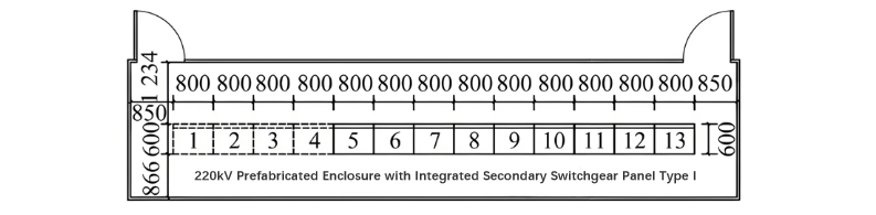
In the 500 kV substation, the 220 kV line protection, bus differential differential protection protection, section - bus - coupler charging protection and measurement and control panels are all integrated and arranged in the secondary prefabricated cabin (for the specific arrangement of the panels, see Figure 1). This secondary prefabricated cabin is arranged in the vicinity of the 220 kV gas - insulated switchgear (GIS) equipment area.
Compared with the conventional secondary relay protection room, the secondary prefabricated cabin realizes the simultaneous construction, simultaneous commissioning and simultaneous completion of the protection and measurement - control panels and the cabin lighting and HVAC (Heating, Ventilation and Air - Conditioning) systems, which greatly shortens the construction period.
1.2 Structure of the Prefabricated Cabin
The prefabricated cabin's exterior uses fiber cement (FC) panels. Its steel - framed walls have 3 - m spaced H - shaped steel columns, with C - type weathering steel or channel steel for support. The wall layers, from outer to inner, are: 12 - mm FC panels, polyethylene seals, 2 - mm cold - rolled steel plates, rock - wool - filled skeletons, and 4 - mm aluminum - plastic panels. The stainless - steel herringbone roof welds to the frame, with bilateral drainage integrated into the roof. A rock - wool - insulated ceiling lies beneath.
The enclosure employs vacuum insulation panels and phase - change materials (PCM). Vacuum panels cut summer AC energy use by 25% and winter use by 50%. PCM's phase - change properties balance temperatures, absorbing heat by day and releasing it at night.
1.3 Internal Wiring of the Prefabricated Cabin
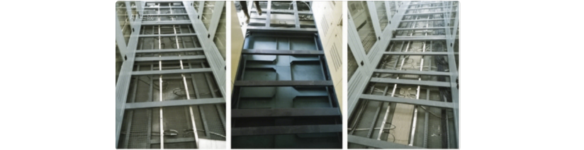
The prefabricated cabin adopts concealed wiring inside. A binding wire net or trough - box structure is arranged in the bottom interlayer of the cabin, used for fixing and binding cables and optical cables. The trough - box structure has an upper and a lower layer, enabling separate laying of cables and optical cables. The bottom structure of the prefabricated cabin is shown in
1.3 Internal Wiring of the Prefabricated Cabin
The prefabricated cabin adopts concealed wiring inside. A binding wire net or trough - box structure is arranged in the bottom interlayer of the cabin, used for fixing and binding cables and optical cables. The trough - box structure has an upper and a lower layer, enabling separate laying of cables and optical cables. The bottom structure of the prefabricated cabin is shown in Figure 2.
In addition, cable troughs for power cables are also set in the interlayers around the cabin near the walls, achieving the physical separation of strong and weak electricity. The cabin manufacturer shall strictly follow the specified cable types to lay all cables from the terminals to the distribution boxes, ensuring the standardization and consistency of wiring.
In addition, cable troughs for power cables are also set in the interlayers around the cabin near the walls, achieving the physical separation of strong and weak electricity. The cabin manufacturer shall strictly follow the specified cable types to lay all cables from the terminals to the distribution boxes, ensuring the standardization and consistency of wiring.
2 Waterproof and Sealing Performance
2.1 Conventional Substations
The roof waterproof performance of conventional substations depends on both the roof shape and the selected waterproof materials. The roof shapes are mainly divided into flat roofs and sloped roofs; there are two main types of waterproof material solutions:
- Solution 1: Adopt the “two - cloth and four - oil” anti - corrosion and waterproof process. First, apply waterproof coatings such as polyurethane and epoxy resin on the inner layer, then lay fine - aggregate concrete, lay a foam plastic insulation layer on the outer layer, and finally level it with cement mortar.
- Solution 2: Based on fine - aggregate concrete pouring, first lay steel fiber cloth and level it with cement mortar inside. Then lay polymer waterproofing membranes on the insulation layer, and finally perform slab pouring and slope - finding treatment.
2.2 Prefabricated Cabin - Type Substations
Compared with conventional substations, the external facade of prefabricated cabin - type substations uses cement fiber boards. The top is a stainless - steel herringbone sloped roof (with a slope of 5%), and the sloped roof is welded integrally with the cabin frame. As a new - type building material, cement fiber boards have excellent fire - resistance and flame - retardancy properties, and are easy to install, efficient in installation, and convenient for later - stage maintenance.
The top drainage of prefabricated cabin - type substations is divided into two forms: centralized drainage and natural drainage:
- Centralized drainage: A water - collecting trough is set on the cabin roof, and drain pipes are equipped at the four corners of the cabin. Rainwater is discharged through the drain pipes.
- Natural drainage: A dripping eave is set on the cabin roof, and no drain pipes are set around.
For the drainage layout, see Figure 3.
3 HVAC System
3.1 Conventional Substation
The relay protection room of a conventional substation uses wall - mounted/split cabinet - type air conditioners with exhaust devices. Fire actions trigger interlocking to cut off HVAC, which auto - restarts after power recovery for continuity.
3.2 Prefabricated Cabin - Type Substation
Equipment in the secondary prefabricated cabin has these traits:
- Dense & high heat : Many protection, measurement - control, and power panels generate continuous heat, raising cabin temp.
- Frequent air exchange : Routine 2 - 3 - day inspections (per “Five Unifications”) mean personnel enter/exit often, disturbing internal humidity.
- Uneven heat : Concentrated heat from protection devices/switches causes temp & humidity differences, needing ventilation.
Solutions:
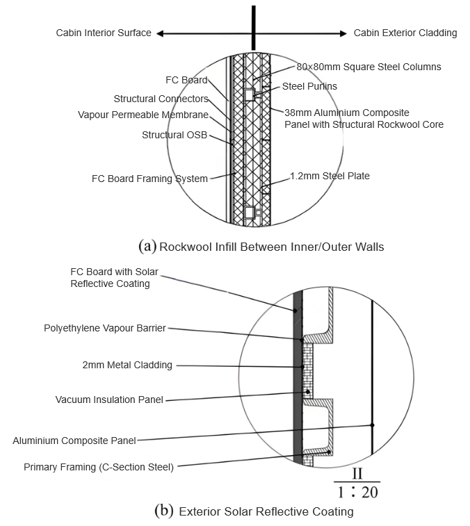
- Passive insulation : Rock wool fills wall layers (Figure 4(a)) and reflective coatings outside (Figure 4(b)) cut heat transfer.
- Active control : Industrial ACs and exhaust fans on both sides balance temp/humidity, reducing condensation.
4 Fire Safety
A building’s fire - resistance depends on components like walls/columns/beams. The fire - resistance rating is the time materials take to lose load - bearing/fire - insulating function under a standard temperature curve. Buildings must meet Code for Fire Protection Design of Buildings; material specs (thickness, etc.) determine this.
4.1 Conventional Substations
Their secondary relay protection/control rooms use reinforced concrete, with minimum fire - resistance Class II and fire hazard Category Wu (non - combustible - related). Equipped with mature fire gear, they meet requirements. Load - bearing walls: non - cohesive porous bricks (5.5h designed, 2.5h min). Columns: reinforced concrete (3h designed, 2.5h min).
4.2 Prefabricated Cabin - Type Substations
Cabins use steel welding, walls filled with non - combustibles, pre - installed fire alarms/probes/gear. Over 500°C, steel loses rigidity/strength, deforms, risking collapse. This makes their fire performance worse than conventional substations.
5 Conclusion
Conventional substations have mature standards (design, insulation, fire inspection) but face civil - work, long - cycle, season - impact issues. Prefabricated cabins, with small footprint, short cycle, flexible layout, are key for modular design.
Still early - stage, prefabricated cabins lack full verification (moisture, fire) and national inspection standards, posing fire risks. So, focus on their fire design, inspection, and operation/maintenance.