• 25-36kW Three Phase 3 MPPTs C&I Grid-tied Inverters
  • 25-36kW Three Phase 3 MPPTs C&I Grid-tied Inverters
25-36kW Three Phase 3 MPPTs C&I Grid-tied Inverters
discuss personally
Model
WN25K-MT
Basic info
Brand Wone
Model NO. 25-36kW Three Phase 3 MPPTs C&I Grid-tied Inverters
Max.Input Voltage 1100V
Max. Input Current per MPPT 30A
Number of MPP trackers 3
Nominal Output Voltage 400V
Max.Efficiency 98.8%
Series C&I Grid-tied Inverters
Product Detail

Description:

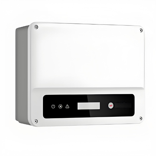
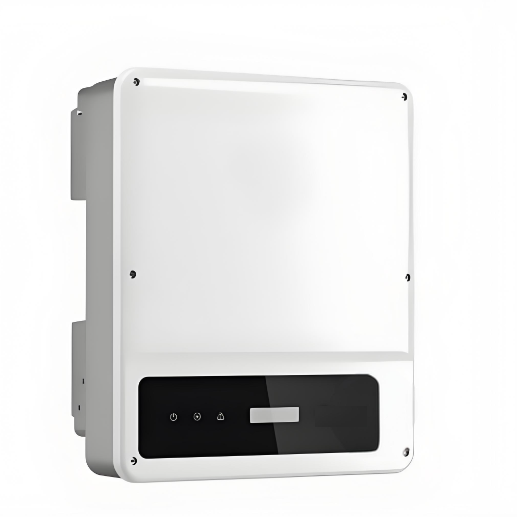
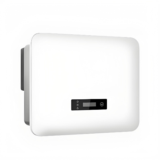
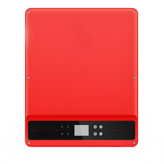
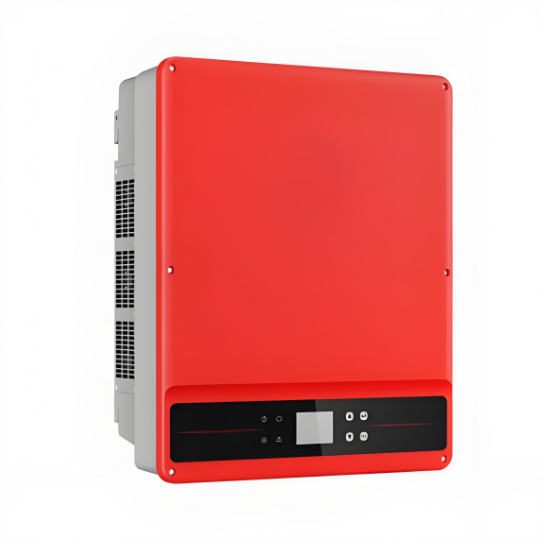
The three-phase inverter is ideal for commercial rooftop system solutions. The SMT series achieves maximum efficiency of 98.8% and features unique design highlights, including solid capacitors, fuse-free design, and optional Arc Fault Circuit Interrupter (AFCI) function. These new features ensure a longer lifespan and a higher safety level of operation, allowing for an improved user experience. With a compact design and weight of just 40 kg, the SMT series is more convenient to install. With a maximum DC input voltage of 1100V, a wider MPPT range for complex rooftops, and a start-up voltage of 180V, the SMT series guarantees an earlier generation of power and a longer working time to maximize long-term returns and profitability in safe operating conditions.

Feature:

Smart Control & Monitoring 

  • String level monitoring. 

  • Dynamic power export limit.

Optimal Generation for Higher Return

  • 98.8% Max. Efficiency.

  •  Up to 130% DC input oversizing & 110%.

 AC output overloading

  • Superb Safety & Reliability.

  • Optional Arc-fault circuit interrupter.

  •  Optional Type II SPD on both DC and AC.

Friendly & Thoughtful Design

  • 40kg compact design.

  • Power line communication optional.

System Parameters:


image.png

image.png

What is G&I grid-tied inverter?

Definition:
A grid-connected inverter is a device that converts direct current (DC) into alternating current (AC) and ensures that the output AC matches the frequency, phase, and voltage amplitude of the power grid. In this way, the converted electrical energy can be directly integrated into the power grid for use by households, enterprises, and the power grid itself.

Working Principle:

  • Input Circuit: The grid-connected inverter receives direct current from solar photovoltaic panels, wind turbines, or other DC power sources.

  • DC/AC Conversion: Through internal power electronic converters (such as inverter bridges), the direct current is converted into alternating current.

  • Synchronization Control: Through advanced control algorithms (such as Phase-Locked Loop, PLL), it ensures that the output alternating current is synchronized with the frequency, phase, and voltage amplitude of the power grid.

  • Output Circuit: The converted alternating current is fed to the power grid, and it is ensured that the output of the inverter complies with the power quality of the power grid.


Know your supplier
Wone
Main Categories
High voltage/Low voltage/Wire cable/Instrument meters/New energy/Tester/Production equipment/Generator/Electrical fittings/Integrated Electrical Equipment
Business Type
Design/Manufacture/Sales
Highest Annual Export (USD)
$50,000,000
Professional Experience
1 years
Workplace
65666m²m²
占位
占位
Related Products
Related Knowledges
Design of Electromagnetic Compatibility Performance for Electronic Voltage Transformers
With the rapid development of power systems, electronic voltage transformers (EVTs), as key measurement devices in power systems, their performance stability and reliability are crucial for the safe and stable operation of power systems. The electromagnetic compatibility (EMC) performance, as one of the core indicators of EVTs, is directly related to the ability of the device to work normally in complex electromagnetic environments and whether it will cause electromagnetic interference to other
Dyson
07/02/2025
Case Analysis of Abnormal Secondary Circuits in Voltage Transformers
1. Fault SituationIn September 2023, as a front - line fault maintenance worker, I detected abnormal voltage on the 10kV Section I bus of a substation during monitoring duty and informed the operation and maintenance team. The monitoring system showed: U0 = 0 kV, Ua = 6.06 kV, Ub = 5.93 kV, Uc = 6.05 kV, Uab = 10.05 kV, Ubc = 5.94 kVMy team and I rushed to the site. We suspected the secondary air circuit breaker of the 10kV Section I bus voltage transformer was closed and found the U - phase fus
Felix Spark
07/02/2025
What are the causes of failure of ferromagnetic voltage transformers in new energy power stations?
By Felix, 15 Years in the Electrical IndustryHi everyone, I'm Felix, and I've been working in the electrical industry for 15 years.From early involvement in traditional substation commissioning and maintenance to now managing electrical system operations for multiple photovoltaic and wind power projects, one of the most frequently encountered devices I deal with is the Electromagnetic Voltage Transformer (PT).The other day, a shift operator at a new energy plant asked me:“We have an electr
Felix Spark
07/02/2025
In which directions will dry-type transformers develop in the future?
By Echo, 12 Years in the Electrical IndustryHi everyone, I'm Echo, and I've been working in the electrical industry for 12 years.From my early days doing commissioning and maintenance in distribution rooms, to later participating in electrical system design and equipment selection for large-scale projects, I’ve witnessed how dry-type transformers have evolved from traditional tools into smarter, greener devices.Recently, a new colleague asked me:“What’s the current state of dry
Echo
07/02/2025
Installation and Commissioning of 10kV Dry-Type Transformers
By James, 10 Years of Electrical Equipment Maintenance ExperienceHi everyone, I’m James, and I’ve been working in electrical equipment fault repair for 10 years.Over the past decade, I’ve worked in factories, substations, and distribution rooms of all sizes, involved in the installation, commissioning, maintenance, and troubleshooting of dry-type transformers. Dry-type transformers are among the most common electrical devices we deal with on a daily basis.Today, a new colleague
James
07/01/2025
What are the reasons for low insulation at the low-voltage side of a dry-type transformer?
Hi everyone, I’m Felix, and I’ve been working in electrical equipment fault repair for 15 years.Over these years, I’ve traveled across factories, substations, and distribution rooms all over the country, troubleshooting and repairing all kinds of electrical equipment. Dry-type transformers are among the most common devices we deal with.Today, a friend asked me:“What does it mean when the low-voltage side of a dry-type transformer has low insulation resistance?”Great
Felix Spark
07/01/2025
×
Inquiry
Download
Experts Electrical is dedicated to serving the personnel in the global power industry.
Join Experts Electrical, not only can you discover power equipment and power knowledge, but also canhnd like - minded friends!