What is the operation mode of the step-up transformer in photovoltaic power generation?

Echo
06/24/2025

1 Overview of Photovoltaic Power Generation Process
In my daily work as a frontline operation and maintenance technician, the photovoltaic power generation process I encounter involves connecting individual solar panels into photovoltaic modules, which are then paralleled through combiner boxes to form a photovoltaic array. Solar energy is converted into direct current (DC) by the photovoltaic array, then transformed into three-phase alternating current (AC) via a three-phase inverter (DC-AC). Subsequently, a step-up transformer increases the voltage to match the requirements of the public power grid, enabling the integration and distribution of electrical energy to grid-connected equipment.
2 Classification of Common Faults in Photovoltaic Power Generation Operation
2.1 Substation Operation Faults
During maintenance, substation faults can be categorized into transmission line faults, busbar faults, transformer faults, high-voltage switch and auxiliary equipment faults, and relay protection device faults. These directly impact the voltage transformation and transmission of electrical energy.
2.2 PV Area Operation Faults
Faults in the PV area often stem from substandard installation practices, such as issues with solar panels, strings, and combiner boxes due to improper installation, inverter malfunctions from inadequate commissioning, and faults in step - up transformer auxiliary equipment. Additionally, oversight during inspections can lead to undetected potential hazards, exacerbating potential failures.
2.3 Communication and Automation Faults
While communication and automation system faults may not immediately affect power generation, they hinder operational analysis, defect detection, and remote control capabilities, posing safety risks that could escalate if unaddressed.
2.4 Geographical and Environmental Faults
Environmental factors can cause equipment deformation due to soil settlement, electrical short circuits from insufficient safety clearances, corrosion from salt spray, insulation degradation from moisture, and short circuits caused by wildlife intrusion.
3 Root Causes of Common Faults
Theoretically, accidents and major faults can be prevented through strict management. However, in practice, electrical safety incidents and equipment failures persist due to:
  • Design flaws in early PV projects resulting from rushed development and lack of experience.
  • Compromised construction quality due to tight schedules, leading to substandard workmanship and long-term operational risks.
  • Inability to assess equipment reliability without comprehensive operational testing, resulting in the use of low-quality components.
  • Skill gaps among maintenance personnel, with many being new hires reliant on outdated training methods, lacking proficiency in fault diagnosis and emergency response.
4 Solutions
Technical strategies to address common faults in PV power stations include:
  • Rigorous upfront planning to ensure designs align with site-specific conditions.
  • Comprehensive infrastructure management with strict contractor vetting and quality control.
  • Stringent equipment qualification to exclude substandard products.
  • Enhanced training programs to improve personnel responsibility and technical expertise.
    Implementation of these measures can significantly reduce fault occurrence.
4.1 Substation Fault Handling
Substation faults follow standard electrical fault management protocols. In the event of busbar outages or line trips, single - busbar substations may experience complete station blackout, triggering islanding protection and inverter shutdown. Operators must:
  • Secure auxiliary power and verify backup systems for DC and communication.
  • Analyze protection device actions to identify fault types.
  • Inspect primary systems, locate faults, and coordinate with grid operators for safe restoration.

4.2 PV Area Fault Causes
Key factors contributing to PV area faults include:
  • Poor installation practices, such as loose connections, substandard components, and inadequate sealing in combiner boxes.
  • Ineffective coordination among installation, wiring, and commissioning teams for inverters and transformers.
  • Environmental degradation, particularly corrosion from coastal salt spray and insulation breakdown.
  • Wear and tear from prolonged operation, including loosening of fan components, terminal blocks, and enclosure latches.
4.3 Fault Prevention Strategies
Preventive measures for electrical equipment faults involve:
  • Ensuring construction quality meets operational standards before handover.
  • Proactive technical supervision and environmental risk mitigation during operation.
  • Cultivating personnel accountability and analytical skills through targeted training.
4.4 Fault Detection and Handling
Hidden faults between solar panels and combiner boxes, which cause energy loss without obvious symptoms, can be detected using clamp meters to measure string currents. Faulty components, fuses, or connections should be promptly replaced.
4.4.1 Combiner Box Faults
Common issues include seal failures, communication module malfunctions, and overheating from loose terminals. Regular inspections during spring maintenance, including resealing and tightening connections, can mitigate summer overheating risks.
4.4.2 Inverter Faults
Inverter failures, often manifesting as shutdowns or startup issues, are prevalent during initial operation. Post-commissioning, overheating due to poor ventilation or component/software malfunctions is typical. Preventive measures include regular filter cleaning and fan inspections.
4.4.3 Step-Up Transformer Faults
Modern dry-type transformers rarely fail, but common issues include ingress of wildlife due to poor sealing, fan malfunctions, and valve latch failures. In coastal or hybrid projects, cable terminations and surge arresters require extra vigilance to prevent collector line outages. Fault prevention relies on routine inspections and technical monitoring.
Echo

As an expert in the application and trends of electrical equipment, I have a profound mastery of knowledge in circuits, power electronics, etc. I possess a comprehensive set of abilities including equipment design, fault diagnosis, and project management. I can precisely grasp the industry's pulse and lead the development of the electrical field.

Research on Application of 10kV Load Switchgear in Distribution Networks
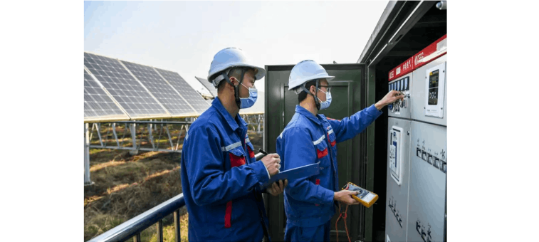
As a frontline worker in power distribution operation and maintenance, I deal with load switches daily—they’re the “gatekeepers” of medium - voltage distribution systems, ensuring stable power supply for users. With rapid economic development, the demand for power system safety and reliability keeps rising. Medium - voltage distribution systems are crucial for grid stability, and load switches (as key line - mounted equipment) play a pivotal role. Their main functions inc
Echo
06/28/2025
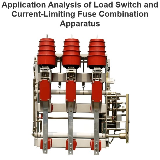
Application Analysis of Load Switch and Current-Limiting Fuse Combination Apparatus
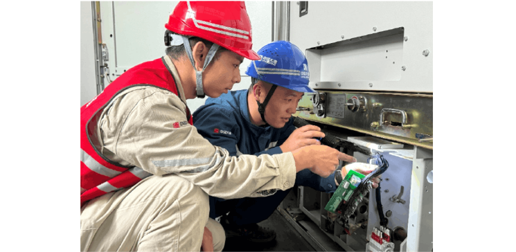
As a front - line technician in loop - network power supply and prefabricated substation operation and maintenance, I deeply understand equipment iteration driven by high - voltage urban expansion. Per theNational Power Supply and Consumption Regulations, for equipment over 250kW or 160kVA transmission capacity, 10(6)kV high - voltage power supply and 220/380V step - down form a necessary pattern, making loop - network units and prefabricated substations key in distribution networks.I. Equipment
Echo
06/27/2025
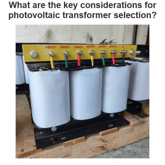
What are the key considerations for photovoltaic transformer selection?
Sizing Principles and Technical Parameters of Photovoltaic TransformersSizing photovoltaic transformers requires a comprehensive consideration of multiple factors, includingcapacity matching, voltage ratio selection, short - circuit impedance setting, insulation class determination, and thermal design optimization. The key sizing principles are as follows:(I) Capacity Matching: Fundamental for Load BearingCapacity matching is thecore prerequisitein sizing photovoltaic transformers. It requires a
Echo
06/27/2025
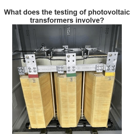
What does the testing of photovoltaic transformers involve?
1. Specificities and Testing Requirements of Photovoltaic TransformersAs a new energy systems technician, I recognize photovoltaic transformers' unique design and application traits: Inverter - output AC carries abundant 5th/7th - order odd harmonics, with PCC harmonic current distortion reaching 1.8% (higher voltage distortion under low load), causing winding overheating and accelerated insulation aging. Photovoltaic systems use TN - S grounding, requiring reliable N - phase output from the sec
Oliver Watts
06/27/2025
Inquiry
Download
Experts Electrical is dedicated to serving the personnel in the global power industry.
Join Experts Electrical, not only can you discover power equipment and power knowledge, but also canhnd like - minded friends!