Circuit breakers are among the most crucial electrical devices in the power system. They are electrical devices capable of interrupting, closing, and carrying the normal current of an operating line, and can carry, close, and interrupt specified abnormal currents (such as short - circuit currents) within a specified time. Good contact in the conductive circuit of a circuit breaker is a vital condition for ensuring its safe operation. If the contact is poor, it can cause the switch to overheat or even burn out, leading to a power outage in the power grid. Whether the contact in the conductive circuit of a circuit breaker is good can be determined through a circuit resistance test. Therefore, measuring the circuit resistance is necessary in preventive tests. Here, the circuit resistance test of a 220kV sulfur hexafluoride (SF₆) circuit breaker is taken as an example for introduction.
2. Current Situation Analysis
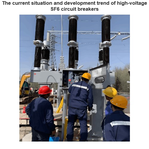
In the currently operating power system, most 110kV and 220kV systems adopt SF₆ circuit breakers. According to the insulation design requirements of the circuit breaker itself and the design requirements of the power system, the height of a 110kV circuit breaker is generally 2.5 meters, and that of a 220kV circuit breaker is typically 4 meters. Additionally, there is a framework height of about 2 meters. The total height of the circuit breaker is between 4 and 6 meters.
To conduct a circuit resistance test on a circuit breaker, ladders and aerial work platforms are necessary. Moreover, for the current inverted - type SF₆ circuit breakers, climbing by personnel is not allowed. Therefore, if the circuit resistance test is carried out using the conventional test method, only an aerial work platform can be used.
3. Summary of Test Methods
(1) Test Principle
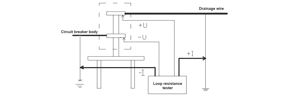
For the circuit resistance test of a circuit breaker, the voltage - drop method is adopted. The principle of the voltage - drop method is that when a direct - current is passed through the circuit under test, a voltage drop will occur across the contact resistance of the circuit. By measuring the current passing through the circuit and the voltage drop across the circuit under test, the contact direct - current resistance value can be calculated according to Ohm's law: R = U/I. The schematic diagram of the circuit resistance test for a circuit breaker is as follows (Figure 1):
Voltage is the difference between one potential point and another. If we assume that the ground is the zero-potential point, then we can simply understand that the applied voltage is an electromotive force. In this case, we only need to apply an electromotive force between the two test points using the testing instrument.
(2) Test Method
The on-site physical connection diagram for the circuit resistance test of the sulfur hexafluoride (SF₆) circuit breaker is as follows (Figure 2):
As is well known, when conducting high-voltage tests on circuit breakers, both sides of the circuit breaker must be reliably grounded. This is a technical measure to ensure safety and is clearly stipulated in the Safety Regulations. Based on the fundamental characteristic that current can only flow through a specific path, during the circuit resistance test of a circuit breaker, we ingeniously utilize the safety measure during operation - the grounding wire - as the current loop. The grounding wire has a cross-sectional area of 25mm², which is sufficient to withstand a large current of 200A, meeting the test requirements.
During the test, we disconnect the grounding point of the grounding wire on one side of the circuit breaker, while maintaining the safe grounding of the working point on the other side. We connect the two current poles of the test instrument to the grounding wires on both sides of the circuit breaker respectively. In this way, current can be applied through the grounding wires on both sides, forming the current loop for the test. Since the grounding point on one side of the circuit breaker has been disconnected during the test, the resistance of the grounding grid is excluded from the test loop, ensuring that the test loop only includes the circuit breaker and guaranteeing the accuracy of the test.
Next is the solution for the test voltage loop. We connect the wires of the test voltage loop to the metal top rod of the insulating rod (the metal top rod has been specially processed to have a pointed tip to ensure good contact with the terminal block of the circuit breaker). Because the circuit resistance value of the circuit breaker itself is extremely small, even a tiny amount of transition resistance can cause significant errors. During the test, the metal top rod of the insulating rod is pressed against the terminal block of the circuit breaker (two insulating rods are required, which are respectively pressed against the upper and lower terminal blocks of the circuit breaker). Since the wires of the test voltage loop are thin and light, they hardly affect the testers' operation of lifting the insulating rods for testing.
The reason why the current loop is formed by using the grounding wires on both sides of the circuit breaker is twofold. Firstly, the current wires are thick and heavy. Secondly, due to the large test current, good contact must be ensured; otherwise, the contact points will be eroded. If insulating rods were used to form the current loop, the increased weight of the insulating rods would make them difficult for testers to operate, and good contact could not be guaranteed.
The test is carried out as follows: First, we clamp the clips of the -I and +I leads onto the grounding wires on both sides of the circuit breaker. This can be completed by the staff standing on the ground, thus establishing the current loop. Then, the testers stand on the framework or mechanism box of the circuit breaker and press the metal top rods of the insulating rods connected to the voltage loop wires against the upper and lower terminal blocks of the circuit breaker respectively. It is crucial to ensure that -U corresponds to -I and +U corresponds to +I. In this way, the test loop is completed.
4 Analysis of Test Results
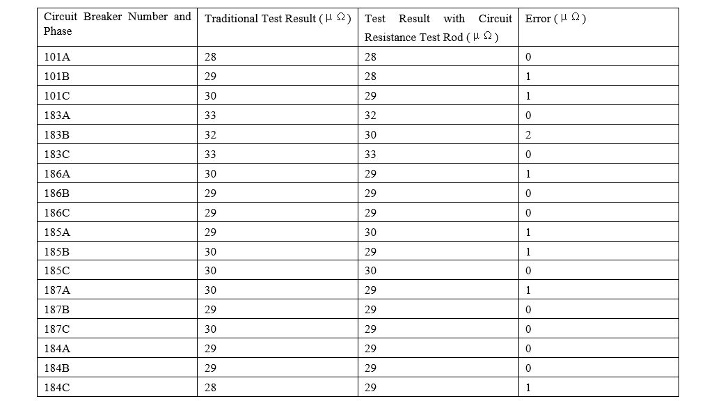
For testers, everything must be evidenced by data. Using specially prepared insulating rods for testing the circuit resistance of circuit breakers, we conducted circuit resistance tests on the 220kV and 110kV circuit breakers at the 220kV Haigeng Substation and 220kV Songming Substation under our jurisdiction.
220kV Haigeng Substation 110kV circuit breaker
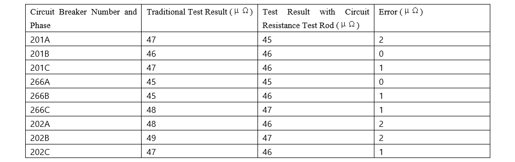
220kV Songming Substation 220kV circuit breaker
220kV Songming Substation 220kV circuit breaker
The test results obtained by the traditional method and the circuit resistance test rod are almost the same, with an error ranging from 1 to 2 μΩ. This error is acceptable, indicating that this method is feasible and accurate.
Comparison between the Circuit Resistance Test of Circuit Breakers Using the Circuit Resistance Test Rod and the Traditional Method
(1) Traditional Test Method
- The traditional method requires workers to climb the circuit breaker or use an aerial work platform. Without climbing or using an aerial work platform, the test leads cannot be connected to the upper and lower terminal blocks of the circuit breaker.
- Working at heights poses certain risks. Firstly, the circuit breaker may break (such incidents have occurred in China). Secondly, there is a risk of personnel falling. Currently, climbing circuit breakers is strictly prohibited, which may prevent the completion of the circuit breaker test.
- When using an aerial work platform, it is restricted by the site. In some substations, the space is very compact, and in some electrical bays, there is not enough room for the aerial work platform to enter, thus preventing the test from being completed and endangering the safe operation of the circuit breaker. Additionally, when operating the aerial work platform, special caution is required as the surrounding equipment is usually live. Sufficient safety distances must be maintained at all times. Moreover, sufficient distances must also be kept from the equipment under outage to prevent damage. The operation of the aerial work platform requires dedicated supervision, which increases the number of required personnel.
(2) Test Using the Circuit Resistance Test Rod
- Workers only need to stand on the framework or mechanism box of the circuit breaker and use the insulating rod with test leads to complete the test. There is no need for personnel to climb the circuit breaker, which significantly reduces operational risks and enhances safety.
- There is no need to use an aerial work platform, which also reduces the risks associated with working at heights, such as the risk of electric shock and the risk of accidentally touching equipment. At the same time, it saves manpower and material resources.
- If an aerial work platform is used, professional personnel are required for driving and setting it up at the work site. After setup and operation, it definitely takes longer than using the circuit resistance test rod for the test. Using the circuit resistance test rod shortens the working time, improves work efficiency, and saves manpower.
5 Conclusion
Through the comparison between the conventional method and the method using the circuit resistance test rod for the circuit resistance test of circuit breakers, the superiority of using the circuit resistance test rod is fully demonstrated. Firstly, the operational risks during work are reduced, and safety is enhanced. Secondly, work efficiency is improved, and manpower and material resources are saved, which reduces costs for the safe operation of the power grid.