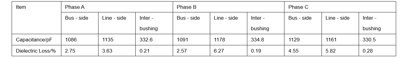
Through a comparative analysis of Table 3, it was found that the capacitance value obtained by the positive - connection test between bushings was relatively close to the actual value. However, affected by the stray capacitance inside the circuit breaker, there was still a certain deviation between the measured value and the calculated value. Nevertheless, from the test results of the parallel capacitances of the interrupting ports among the ABC phases, the differences in capacitance among the three phases were relatively small. Based on this, it was preliminarily judged that the state of the parallel capacitor of the C - phase interrupting port was normal.
(5) Inspection Inside the Circuit Breaker Tank
At the fault - handling site, the gas of phase C of the faulty circuit breaker was professionally recovered. Subsequently, an endoscope was used to conduct an in - depth inspection inside the tank. After a detailed inspection, it was found that the closing resistance near the Ⅱ - bus side had a breakdown. Black resistance chip fragments were scattered at the bottom of the tank. In addition, it was also found that the polytetrafluoroethylene sheath of one of the closing resistances had cracked and fallen to the bottom of the tank.
2.1.1 Inspection of the Disconnect Switch
After a detailed on - site inspection, obvious burning marks were found on the arcing finger parts of the moving contacts on both sides of phase C of the disconnect switches on both sides of the faulty circuit breaker. Subsequently, by manually operating the disconnect switch of phase C on - site, the entire operation process was smooth without any jamming. Moreover, during the inspection, it was observed that there was no welding phenomenon between the moving and static contacts. After the opening operation was completed, a detailed inspection of the static contact base and the contact fingers was further carried out, and no serious burning marks were found.
2.1.2 Inspection of Secondary Equipment
At 12:31:50.758 on June 18, 2022, phase C of the faulty circuit breaker in the 750kV substation was grounded. After the fault occurred, the line fiber - optic differential protection and the bus differential protection of 750kV Bus - Ⅱ both operated correctly. Through an in - depth analysis of the fault current and the operation of the bus differential protection and the line protection, when the disconnect switch was in the closed state (during which the system voltage remained stable without over - voltage), it was observed that 750kV Bus - Ⅱ supplied fault current to the fault point. It is worth noting that CT₇ and CT₈ involved in the bus differential protection of the faulty circuit breaker did not detect the existence of fault current. Based on this observation, it was determined that the fault point should be in the area between circuit breaker CT₇ and the bus. Meanwhile, CT₁ and CT₂ for line protection detected the existence of fault current, and the value of the fault current reached a primary current of 4.5kA. Therefore, it was further inferred that the fault point was in the area between CT₂ of the faulty circuit breaker and the interrupting port on the Ⅱ - bus side of the circuit breaker. This inference was consistent with the location of the fault point found in the on - site internal inspection.
2.2 Dismantling Inspection
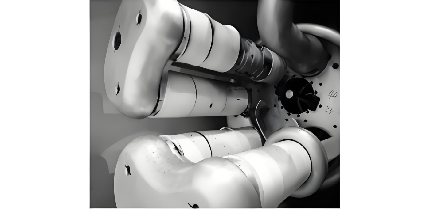
As shown in Figure 2, during the inspection of the inside of the tank during the circuit breaker dismantling process, fragments of the closing resistance and its protective sheath were observed scattered around. Some resistance chips of the fourth - column closing resistance, which was connected in parallel with the main interrupting port on the mechanism side of the circuit breaker, had exploded, and the corresponding two resistance protective sheaths had also ruptured. End shield A of the resistance showed traces of discharge ablation on the inner wall of the tank, and shield B also had traces of discharge ablation on A. In addition, the surface of the insulating support rod showed blackened traces. By checking the assembly, factory test, and on - site installation data of the circuit breaker, and inspecting the main insulating parts, no abnormalities were found.
3 Fault Cause Analysis
Through dismantling analysis, the following conclusions were drawn: During the closing process of the disconnect switch, the end shield A of the resistance first discharged to the inner wall of the tank. This led to abnormal currents in the fourth, third, and second - column closing resistances. Subsequently, shield B discharged to A, causing the second and third - column resistances to short - circuit, and the current was mainly concentrated in the fourth column. This phenomenon caused the temperature of the resistance chips in the fourth column to rise sharply, eventually leading to explosion, and the resistance protective sheath broke and fell off. During the discharge process, the generation of high - temperature arcs caused the surface of the insulating support rod to become blackened.
The tank - type circuit breaker can withstand a lightning impulse voltage of up to 2100kV. During the normal closing process of the disconnect switch, although over - voltage may occur, under normal operating conditions, this level of over - voltage is not sufficient to trigger the discharge mechanism of the circuit breaker. However, through in - depth analysis and inference, it is preliminarily suspected that there may be foreign objects inside the tank. These foreign objects may have an adverse impact on the electric field distribution, causing the electric field to distort and exceeding the insulation strength that the SF₆ gas gap can withstand. In this case, end shield A of the resistance may first discharge to the inner wall of the tank. Considering that the foreign objects inside the tank may be hidden in imperceptible crevices, when the disconnect switch is closed with power on, the over - voltage generated may, under the action of the electric field force, move the foreign objects to areas with a stronger electric field, thereby causing electric field distortion and leading to the occurrence of discharge phenomena.
4 Conclusion
Given the extensive application of advanced switchgear in the power system, accidents such as tripping of tank - type circuit breakers and GIS equipment due to foreign objects occur frequently. To prevent such faults, it is necessary to strengthen live - line detection work, especially increasing the detection frequency for circuit breakers that operate frequently. At the same time, during on - site acceptance, it should be strictly checked whether the equipment has completed 200 mechanical operations to ensure the running - in of the mechanism and avoid the adverse effects of metal debris on the operation of the equipment after commissioning.