MV & HV Cable Termination to Equipment & Joints

General Problems and Considerations in Electrical Termination
When it comes to terminating electrical connections in indoor switchgears, electric motors, power transformers, instrument transformers, and other medium - voltage (MV, where the voltage range is(1 kV<V<60 kV) and high - voltage (HV, with V≥60 kV ) equipment, several challenges emerge. These issues often stem from the complexity of termination designs, especially those related to switchgears. To address these concerns effectively, close coordination with the equipment manufacturer is not just advisable but essential.

Factors to Consider in Electrical Machine Termination and Underground - to - Overhead Cable Transitions
Factors in Electrical Machine Termination
When terminating electrical machines, a comprehensive set of factors must be carefully considered to ensure safe, reliable, and efficient operation:
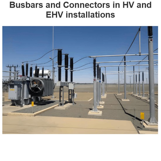
Bus and Supporting Structures: The design, material, and strength of the busbars and their supporting structures are crucial. They need to withstand electrical currents, mechanical stresses, and potential short - circuit forces while maintaining proper alignment and stability.
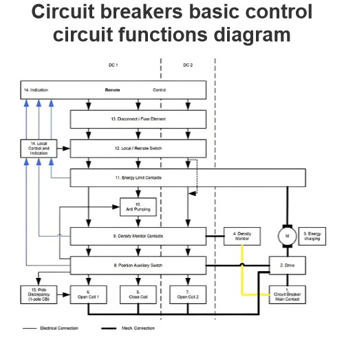
Circuit Breaker Insulation Structure: The integrity of the insulation within circuit breakers is vital for preventing electrical breakdowns. It must be able to withstand the rated voltage, transient overvoltages, and environmental conditions without failure.
PD (Partial Discharge) Analysis: Conducting partial discharge analysis helps detect early signs of insulation degradation. Partial discharges can indicate potential weaknesses in the insulation system, which, if left unaddressed, could lead to catastrophic failures.
Insulation Material: The choice of insulation material, whether it is oil, sulfur hexafluoride (SF6), or vacuum, has a significant impact on performance. Each material has its own advantages and limitations in terms of insulation strength, arc - quenching capabilities, environmental impact, and maintenance requirements.
Wedging System Condition: The wedging system, which secures components in place, must be in good condition. A faulty wedging system can lead to loose connections, increased electrical resistance, and potential overheating.
Cooling Gas Type: For machines that rely on gas - based cooling systems, the type of cooling gas used affects heat dissipation and overall performance. Different gases have varying thermal conductivities and heat - carrying capacities.
Proximity of Grounded Components to High - Voltage Conductors: The location of grounded components in relation to high - voltage conductors is critical. Close proximity can increase the risk of electrical leakage, flashovers, or interference, necessitating proper insulation and spacing.
Terminations for Transition of Underground Cables to Overhead Lines
Terminations for the transition of underground cables to overhead lines, commonly referred to as OH/OG terminations, play a key role in electrical distribution networks. These terminations are typically designed for systems with rated voltages of up to 36 kV. Their primary functions include connecting the distribution system to pre - assembled indoor or outdoor switchgears and facilitating the routing of electrical power while avoiding the need for overhead lines to traverse urban areas.
OH/OG terminations are compatible with both oil - paper and cross - linked polyethylene (XLPE) insulated cables, which can be either single - core or three - core. They are installed outdoors and are mounted on metallic structures that are firmly anchored to overhead line poles made of wood, concrete, or metal, as illustrated in Figure 1.
An essential safety requirement for OH/OG terminations is that their metallic structures must be properly grounded. This grounding serves to protect against electrical shocks, dissipate fault currents, and ensure the overall electrical safety of the system.

Requirements for OH/OG Metallic Structures and Cable Installations, and Elbow Terminations
OH/OG Metallic Structure and Cable Installation Requirements
The height of the OH/OG (Overhead/Underground) metallic structure is not arbitrary; it must strictly adhere to the minimum insulation safety distance to the ground as defined by relevant industry standards. This compliance is crucial for ensuring the safety of people, equipment, and the overall electrical system, preventing electrical hazards such as accidental contact or arcing to the ground.
When installing cables for OH/OG terminations, they should be positioned on the side of the pole that faces away from oncoming traffic. This placement minimizes the risk of damage from vehicles, thereby enhancing the reliability and longevity of the electrical infrastructure. Additionally, throughout both the installation process and after the cables are in their final position, it is imperative that they are not bent beyond the manufacturer - specified minimum internal bending radius. Failing to meet this requirement can cause internal damage to the cable insulation and conductors, potentially leading to electrical failures. In some cases, to ensure that the minimum bending radius is maintained, taller poles may be necessary, adding an extra consideration in the planning and installation phases. Moreover, OH/OG terminations must be designed with animal - proofing measures in place. This safeguards the cables from damage caused by animals, which could otherwise result in power outages and safety risks.
Elbow Terminations
Cable terminations are commonly used to connect cables to the terminals of various equipment, including transformers, motors, and pre - assembled switchgears. However, due to the specific conditions of the electrical installation or the nature of the equipment terminals, there are instances where the cable connection to the bushings needs to be sealed. In such situations, elbow terminations, as depicted in Figure 2, are the preferred choice. These specialized terminations not only provide a secure electrical connection but also offer the necessary sealing functionality, protecting the electrical system from environmental elements and ensuring its stable operation.

Elbow Terminations and Their Application in Ring Main Units (RMUs)
Elbow terminations serve a crucial and specialized purpose, particularly when it comes to connecting cables to the bushings of Ring Main Units (RMUs). RMUs are compact, self - contained, and fully insulated switchgear systems that typically utilize sulfur hexafluoride (SF6) as the insulating medium. Widely employed in secondary distribution networks, these units play a vital role in managing and distributing electrical power at the local level.
One of the key features of RMUs is their design for internal arc withstand, which enhances the safety and reliability of the electrical system. The live parts of RMUs are engineered to be maintenance - free, reducing the need for frequent interventions and minimizing downtime. Additionally, their modular nature allows for easy expansion at the installation site, enabling the system to adapt to changing power demands over time.
The switching and protection functions within RMUs are accomplished through the use of switch - disconnectors in combination with fuses or circuit breakers. This configuration ensures that the electrical system can be safely isolated, faults can be quickly detected and cleared, and the integrity of the distribution network is maintained.
Elbow terminations are not only useful for connecting cables to RMU bushings but also find application when multiple cables need to be linked to the same bushing of electrical equipment. As illustrated in Figure 3, these terminations provide a practical and reliable solution for such complex cable - to - equipment connections, facilitating the efficient distribution of electrical power while maintaining the integrity and safety of the overall system.

Elastimold Cable Joints & Terminations
Elastimold is a well - known brand that offers a comprehensive range of equipment and accessories for cable splicing and termination, designed for rated voltages of up to 36 kV.
Elastimold cable terminations come in both single - piece and modular designs. These versatile models are suitable for various applications, including the transition from underground cables to bare overhead conductors, connections to live - front equipment, and elbow connections, making them adaptable for both indoor and outdoor use. They can be seamlessly integrated into oil, SF6, and air - insulated high - voltage switchgear, as well as transformers, motors, and capacitors.
The designs of Elastimold products incorporate advanced silicone rubber insulating materials. These materials provide essential resistance against creep, electrical strikes, weathering, and contamination, ensuring reliable performance even in the harshest conditions. The compact and lightweight nature of Elastimold units allows for easy installation in confined spaces and enables free - hanging applications.
Elastimold devices are also ATEX - certified. ATEX, derived from the French title of the 94/9/EC (European Commission) directive "Appareils destinés à être utilisés en ATmosphères Explosibles" (Equipment to be installed in explosive atmospheres), these high - voltage bushings are suitable for use within oil or air - insulated switchgear and transformers in hazardous areas, such as those found in the oil, gas, and petrochemical industries. The manufacturing of Elastimold equipment adheres to international standards set by IEC (International Electrotechnical Commission), ANSI/IEEE (American National Standards Institute/Institute of Electrical and Electronics Engineers), and CENELEC (European Committee for Electrotechnical Standardization).
Elastimold offers several specialized devices for specific applications:
Separable Elbow Connectors and Accessories: These are load - break connectors that provide a convenient means of connecting and disconnecting cables and equipment in power distribution systems. Load - break elbows are designed for energized operation using standard hot - stick tools, enabling load make/break operations and providing a visible disconnect. The components can be isolated using insulated caps, plugs, and parking bushings.
Metal Oxide Varistor (MOV) Surge Arresters: These arresters are fully shielded and fully - submersible, designed for overvoltage protection. They feature 200 A separable connector interfaces for easy attachment to other Elastimold accessories. Elastimold arresters offer high - voltage protection against lightning and switching surges for transformers, cables, equipment, and other components typically found in underground power distribution systems. Proper placement, voltage selection, and coordination with riser pole arresters can significantly enhance protective margins and minimize damaging surge voltages. Typical applications include installing arresters at the end of a radial system or at both ends of an open point on a loop system, with additional arresters added at strategic upstream locations for optimal protection.
Fused Elbows: These combine replaceable current - limiting fuses for current protection in OH/OG cable terminations with 200 A separable connector interfaces for compatibility with other Elastimold accessories.
Raychem is another commonly recognized brand in the field of cable splicing and termination equipment.
Terminations for GIS (Gas Insulated Substations)
When the available space for substation installation is limited or environmental conditions are extremely harsh, a Gas Insulated Substation (GIS) is often the preferred solution. GIS is a compact, multi - component assembly housed within a grounded metallic enclosure. It contains bus bars, circuit breakers, isolators, and instrument transformers, with compressed sulfur hexafluoride (SF6) gas serving as the primary insulation medium, ensuring reliable phase - to - ground insulation. While GIS are typically installed indoors, outdoor models are also available.
GIS units are equipped with cable termination enclosures where cable terminations are installed. According to IEC Standard 60859, both the enclosures and cable terminations must meet specific dimension requirements to ensure interchangeability. Cable terminations for GIS are suitable for gas, oil - paper, and XLPE - insulated cables and share many components with the cable joints previously discussed.
Features of GIS Cable Terminations
The main features of GIS cable terminations include:
Cable Lug: Facilitates the connection between the cable conductor and the termination.
Box Body: Typically made of aluminium alloy or a similar material, providing structural support and protection.
Reliable Support Insulator: High - grade, non - tracking epoxy insulators offer excellent mechanical and electrical properties. These insulators are compatible with SF6 gas by - products, ensuring a long service life for the termination. Their design also allows for an optional cable shield break.
Filling Compound: Such as transformer oil, polybutene oil, or similar substances, which help in insulation and stress relief.
Stress Control Cone with Bundle Tape: Manages electrical stress at the cable insulation - termination interface.
Rigid Cable Support: The connector is securely locked in place by a threaded hood at the top of the support insulator. This design ensures that the electrical connection between the GIS and the termination is not subjected to mechanical forces from the cable.
Positive Sealing System: A double "O" ring sealing system is employed to seal the termination oil compartment from the GIS SF6 compartment. Fully retained gaskets are compressed to prevent the ingress of atmospheric elements into the termination interior.
Earthing Clamp: Provides a secure connection for earthing purposes.
Figure 4 illustrates a schematic of a GIS cable termination. Some models available on the market do not require the use of oil, eliminating the need for an oil housing.

Sealing, Connection, and Installation Requirements for GIS Cable Terminations
Sealing System
The sealing system of GIS cable terminations is of paramount importance and must be meticulously designed. Its primary function is to prevent the leakage of oil or gas into the GIS. A compromised seal could lead to insulation failures, gas loss, and potential safety hazards. By ensuring a robust and reliable sealing mechanism, the integrity of the GIS environment and the overall electrical system is maintained.
Mating Connection Piece
The GIS supplier is responsible for providing a mating connection piece that is specifically designed to be fitted to the cable end. This component is crucial for establishing a secure and electrical connection between the cable and the GIS. The precise design and compatibility of the mating connection piece are essential to ensure seamless integration and optimal performance of the cable - GIS interface.
Isolation and Testing Facilities
To guarantee the safety and reliability of the electrical system, proper facilities must be provided to safely isolate a feeder cable. This isolation capability is necessary during maintenance, repairs, or fault - finding operations. Additionally, provisions should be made to connect a high - voltage test cable to either the GIS or the cable itself. These testing facilities enable routine inspections and diagnostic tests to assess the condition of the cable and the GIS, helping to identify potential issues before they escalate into major problems.
Required Tools and Accessories for GIS Termination Installation
For the successful installation of GIS cable terminations, a specific set of proper tools and accessories is indispensable:
Panduit Pliers: These pliers are specifically designed for installing bundle tape around the stress cone. The accurate application of the bundle tape is crucial for managing electrical stress and ensuring the long - term reliability of the termination.
Circlip Pliers: Used for the installation of the top fitting, circlip pliers provide the necessary grip and precision to secure this important component in place.
Adapter Flange: The adapter flange plays a key role in facilitating the connection between different components, ensuring a proper fit and alignment within the GIS termination system.
Top Fitting Removal Kit: This kit is essential for maintenance and repair operations, allowing for the safe and efficient removal of the top fitting when required.
Re - assembly Kit: The re - assembly kit contains all the necessary components and hardware to put the termination back together after maintenance or repairs, ensuring that all parts are replaced correctly.
Earthing Kit: An earthing kit is vital for establishing a secure electrical connection to the ground, which is essential for the safety of the electrical system and personnel.
Screen Connection: The screen connection ensures the proper grounding and shielding of the cable, reducing electromagnetic interference and enhancing the overall performance of the cable - GIS system.
The Electricity Encyclopedia is dedicated to accelerating the dissemination and application of electricity knowledge and adding impetus to the development and innovation of the electricity industry.