Important points in engineering studies in high voltage gas insulated switchgear (GIS)
Engineering Studies in Gas - insulated Switchgear (GIS)
Once the electrical engineer has defined the preliminary configuration of the GIS and determined and specified the primary equipment data, additional studies related to the engineering aspects, as well as the logistics of delivery and installation, must be carried out.
The most crucial engineering studies are summarized as follows:
1. Transient Recovery Voltage (TRV) Conditions
The electrical engineer should stipulate that the manufacturer conducts a TRV study. This study aims to assess the worst - case rate of rise of recovery voltage (RRRV) and the maximum peak voltage across the circuit breakers, taking into account the transient response of the electrical network surrounding the GIS. The calculated TRV values need to be compared with the TRV ratings guaranteed by the circuit breaker's test report and with the standard TRV envelopes available in industry standards.
The TRV experienced by a circuit breaker is the voltage across its terminals after current interruption. The shape of the TRV waveform is determined by the characteristics of the electrical network around the circuit breaker. Generally, the TRV stress on a circuit breaker depends on the fault location, the magnitude of the fault current, and the switching configuration of the switchgear.
Since TRV is a decisive parameter for successful current interruption, circuit breakers are typically type - tested in a laboratory to endure a standardized TRV. This standardized TRV is defined by a four - parameter envelope (a two - parameter envelope for circuit breakers rated up to 100 kV). The first period features a high rate of rise, followed by a subsequent period with a lower rate of rise. The slope of the first period of the TRV envelope is defined as the rate of rise of recovery voltage (RRRV). In cases where the amplitude of the short - circuit - breaking current is extremely low, two - parameter envelopes must be considered to evaluate the TRV stress on a circuit breaker.
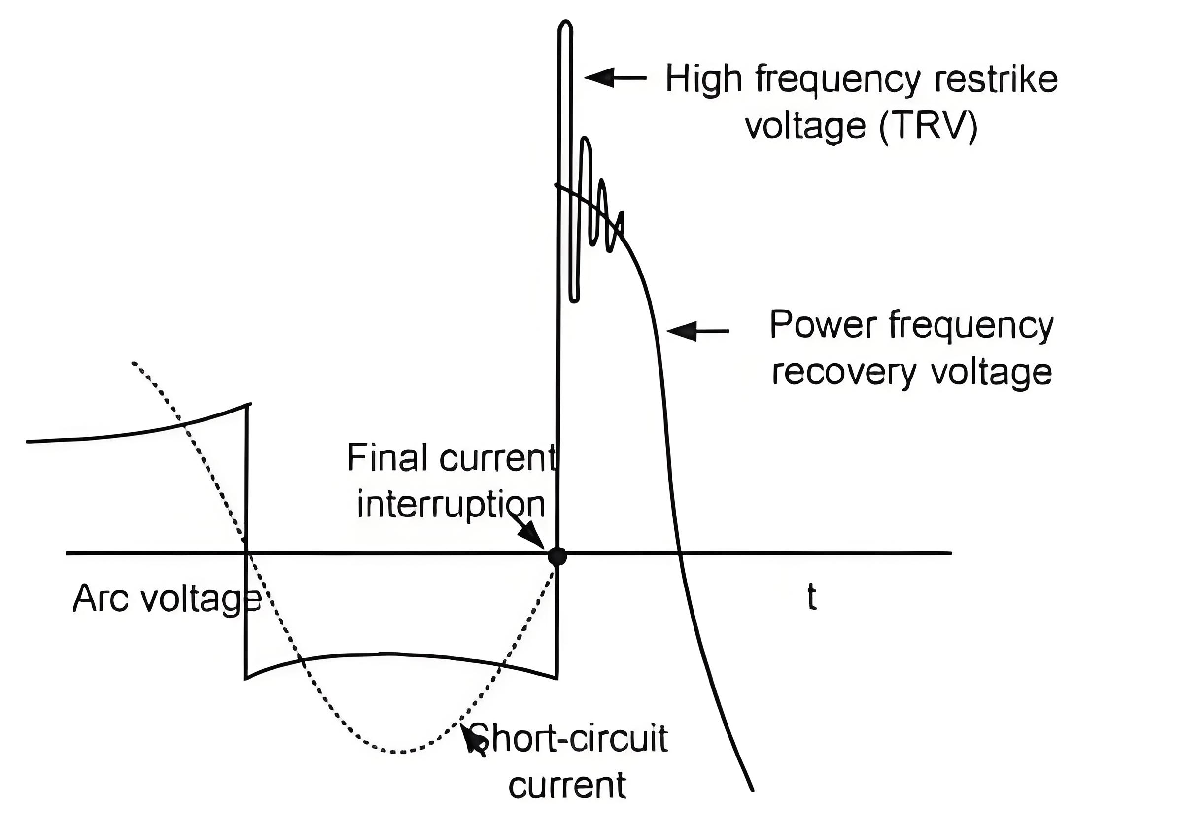
Figure 1: TRV Curve in High - Voltage Circuit Breaker
The objective of this study is to assess the worst - case RRRV and the maximum crest voltage across the circuit breakers within the GIS, based on the transient response of the electrical network surrounding the switchgear.
For further details regarding TRV, you can refer to this article.
2. Very Fast Transient (VFT) Conditions
The electrical engineer must require that the manufacturer conducts a VFT study. In gas - insulated switchgear (GIS), very fast transient (VFT) overvoltages with oscillation frequencies in the MHz range can occur during disconnect switch operations. This is due to the rapid voltage collapse within a few nanoseconds and the length and coaxial design of the GIS.
In the area near the operated disconnect switch, frequencies of over 100 MHz may be generated. At locations farther inside the GIS, frequencies in the range of several MHz can be anticipated.
The frequencies and amplitudes of the VFT are determined by the length and design of the GIS. Owing to the traveling - wave nature of this phenomenon, the voltages and frequencies vary from one location to another within the GIS.
High amplitudes are likely to occur when long segments of gas - insulated buses are switched and when there are tapped buses at the source of the main bus section. If the natural frequencies of the source and the switched end of the bus are similar and the voltage difference across the disconnect switch is large, a significant voltage difference will be present during the opening of the disconnect switch. Generally, the highest amplitudes of the VFT are found on open GIS sections.

Figure 2: Example of VFTO Waveform in 750 kV GIS
The aim of this study is to simulate the VFT overvoltages within the GIS that are generated when energizing switchgear segments using disconnect switches. Additionally, VFT overvoltages resulting from circuit breaker switching operations should be computed.
3. Insulation Coordination Studies
The electrical engineer must stipulate that the manufacturer conducts insulation coordination studies. Such a study is necessary to confirm the location and quantity of GIS metal - enclosed type surge arresters, which are crucial for safeguarding the GIS equipment, any interconnected underground cable circuits, and other air - insulated equipment.
The insulation coordination study examines the overvoltage stresses present at the gas - insulated switchgear, its bays, and cables. These stresses are induced by lightning surges approaching the substation and the lines connected to it. Thus, for several specified substation configurations, including the normal operating configuration, the maximum voltage stresses within the GIS and at the bays, caused by typical lightning strokes (such as remote strokes, direct strokes to conductors, and strokes to the last towers of overhead lines), should be simulated.
The appropriate insulation coordination level should be validated by comparing the insulation levels of individual equipment with the maximum overvoltage stresses anticipated. This comparison should consider the maximum correction and safety factors as per industry standards.
4. Thermal Rating Calculations
The electrical engineer should require that the manufacturer offers thermal rating calculations for all equipment and devices in the main current paths. These thermal rating calculations need to be determined in line with the facility rating methodology of the user and the Regional System Operating Authority.
5. Effects of Ferro - resonance
The electrical engineer must specify that a study be carried out to ascertain whether there is a possibility of Ferro - resonance occurring in relation to the switching in and out of service of potential transformers in the GIS. The study should not only indicate the severity of the condition but also recommend mitigation measures, such as the use of tuned inductors.
6. GIS Resistance and Capacitance
The electrical engineer should demand that the manufacturer provide the calculated and measured capacitance and resistance values for each component in the GIS. This includes, but is not limited to, bushings, bus runs, switches, and circuit breakers.
7. Seismic Calculations
The electrical engineer should require that the manufacturer supplies all documentation regarding seismic design testing (as specified by the manufacturer in the GIS documentation).
8. Electromagnetic Compatibility
The electrical engineer should specify that the manufacturer conducts studies on shielding and mitigation procedures to address interference with control, protection, diagnostics, and monitoring equipment.
9. Civil Engineering Aspects
The engineer should request that the manufacturer furnishes documentation for any special civil designs necessitated by specific site conditions to accommodate the GIS.
10. Grounding and Bonding
The electrical engineer should specify that the manufacturer conducts grounding studies in accordance with the current version of IEEE Standard 80. The manufacturer must ensure that the GIS equipment grounding complies with the National Electric Safety Code C2 and IEEE Standard 80.
All studies should be presented in formal reports and forwarded to the user within the specified time frame after the contract is awarded. All relevant documentation, including but not limited to calculations, curves, assumptions, graphs, and computer outputs, should be provided to support the conclusions drawn.
11. Logistics Studies
- Transport, storage, and erection facilities for gas - insulated switchgear: Analyze and plan for the means of transporting the GIS components to the site, the appropriate storage conditions before installation, and the erection facilities required for proper setup.
- Demands imposed by the service and maintenance of the gas - insulated switchgear and possible future extensions: Consider the requirements for routine service and maintenance of the GIS, as well as any provisions needed for potential future expansions.
- Quality assurance, testing procedures during manufacture, and especially on - site testing: Ensure quality control during the manufacturing process and define comprehensive testing procedures, with a particular emphasis on on - site testing to guarantee the proper functioning of the GIS.
Figure 2 presents an example of a VFTO curve in a 750 - kV GIS (please refer to this post).
Figure 1 depicts a transient voltage recovery curve after the final current extinction in a high - voltage circuit breaker.