Definition and Types of Tachometers
Definition
A tachometer is a device used to measure the rotational speed or angular velocity of a machine to which it is coupled. Its operation is based on the principle of relative motion between the magnetic field and the shaft of the connected device. As the shaft rotates, this relative motion induces an electromotive force (EMF) in a coil placed within the constant magnetic field of a permanent magnet. The magnitude of the induced EMF is directly proportional to the rotational speed of the shaft, enabling the measurement of the machine's speed.
Types of Tachometers
Tachometers can be broadly classified into two categories: mechanical and electrical.
-
Mechanical Tachometer: This type of tachometer measures the shaft's speed in terms of revolutions per minute (RPM). It provides a direct mechanical indication of the rotational speed, often through a mechanical linkage and a pointer on a calibrated dial.
-
Electrical Tachometer: An electrical tachometer converts angular velocity into an electrical voltage. Compared to mechanical tachometers, electrical tachometers offer several advantages, such as higher accuracy, easier integration with electronic control systems, and the ability to transmit speed information over longer distances. As a result, they are widely used for measuring the rotational speed of shafts. Depending on the nature of the induced voltage, electrical tachometers can be further divided into two subtypes:
-
AC Tachometer Generator
-
DC Tachometer Generator
DC Tachometer Generator
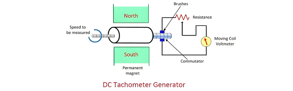
The DC tachometer generator comprises several key components: a permanent magnet, an armature, a commutator, brushes, a variable resistor, and a moving - coil voltmeter. To measure the speed of a machine, its shaft is coupled with the shaft of the DC tachometer generator.
The working principle of the DC tachometer generator is based on electromagnetic induction. When a closed - loop conductor moves within a magnetic field, an EMF is induced in the conductor. The magnitude of the induced EMF is determined by two factors: the amount of magnetic flux linked with the conductor and the rotational speed of the shaft. As the shaft rotates, the armature within the DC tachometer generator moves through the magnetic field of the permanent magnet, generating an EMF that is proportional to the shaft's speed. This induced EMF is then converted into a DC voltage by the commutator and brushes, which can be measured by the moving - coil voltmeter or further processed by electronic circuits for various applications.
Operation and Functioning of DC Tachometer Generator
In a DC tachometer generator, the armature rotates within the unchanging magnetic field of a permanent magnet. As the armature revolves, electromagnetic induction takes place, inducing an electromotive force (emf) in the coils wound around it. Significantly, the magnitude of this induced emf is directly proportional to the rotational speed of the shaft to which the armature is coupled; the faster the shaft spins, the greater the induced emf.
The commutator, in conjunction with the brushes, plays a crucial role in the generator's operation. It transforms the alternating current (AC) generated in the armature coils into direct current (DC). This conversion is essential as it allows for a more straightforward and consistent measurement of the electrical signal. The moving - coil voltmeter is then employed to measure the induced emf, providing a quantifiable output that corresponds to the shaft's rotational speed.
Notably, the polarity of the induced voltage carries important information. It determines the direction of motion of the shaft. For instance, a positive polarity might indicate clockwise rotation, while a negative polarity could signify counterclockwise rotation. To safeguard the voltmeter and ensure accurate measurements, a resistance is connected in series with it. This resistor limits the flow of the potentially high - current generated by the armature, preventing damage to the measuring device and maintaining the integrity of the measurement process.
The emf induced in the DC tachometer generator can be expressed by the following formula:
Where, E – generated voltage
Φ – flux per poles in Weber
P- number of poles
N – speed in revolution per minutes
Z – the number of the conductor in armature windings.
a – number of the parallel path in the armature windings.

Advantages and Disadvantages of DC Tachometer Generator and Introduction to AC Tachometer Generator
Advantages of the DC Tachometer Generator
The DC tachometer generator offers several notable benefits, which are outlined as follows:
- Indication of Shaft Rotation Direction: The polarity of the induced voltages serves as a clear indicator of the direction of rotation of the shaft. This feature provides valuable information about the rotational dynamics of the machine being measured, enabling operators to monitor and control the system more effectively.
- Use of Conventional Voltmeter: A conventional DC type voltmeter can be employed to measure the induced voltage. This simplicity in measurement equipment reduces the complexity and cost associated with setting up the measurement system, making it accessible and easy to use for a wide range of applications.
Disadvantages of the DC Tachometer Generator
Despite its advantages, the DC tachometer generator also has certain drawbacks that need to be considered:
- Maintenance Requirements: The commutator and brushes, which are essential components for converting the alternating current generated in the armature into direct current, require periodic maintenance. Over time, these components can experience wear and tear due to mechanical friction and electrical arcing, leading to reduced performance and potential failures if not properly maintained.
- Output and Input Resistance Issues: The output resistance of the DC tachometer is typically higher compared to its input resistance. In situations where a large current is induced in the armature conductor, this can cause distortion of the constant magnetic field of the permanent magnet. Such distortion can lead to inaccuracies in the measurement of the induced emf and, consequently, errors in determining the rotational speed of the shaft.
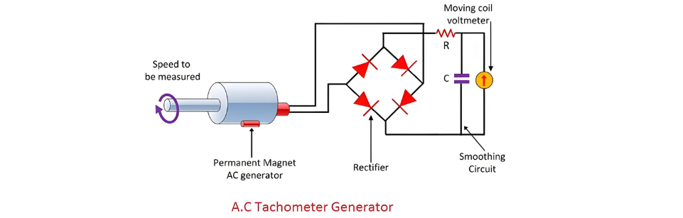
AC Tachometer Generator
The DC tachometer generator's reliance on commutators and brushes gives rise to several limitations. To address these issues, the AC tachometer generator was developed. An AC tachometer generator features a stationary armature and a rotating magnetic field. This design eliminates the need for commutators and brushes, thereby overcoming many of the maintenance and performance problems associated with DC tachometers.
As the rotating magnetic field interacts with the stationary coils of the stator, an electromotive force (EMF) is induced. Both the amplitude and frequency of the induced emf are directly related to the speed of the shaft. This relationship allows for the measurement of angular velocity by either analyzing the amplitude or the frequency of the induced electrical signal.
The following circuit is utilized to measure the speed of the rotor by focusing on the amplitude of the induced voltage. First, the induced voltages are rectified to convert them from alternating current to direct current. Subsequently, the rectified voltages are passed through a capacitor filter, which effectively smoothens out the ripples in the rectified voltage waveform, providing a more stable and accurate measurement of the induced voltage amplitude related to the shaft's rotational speed.
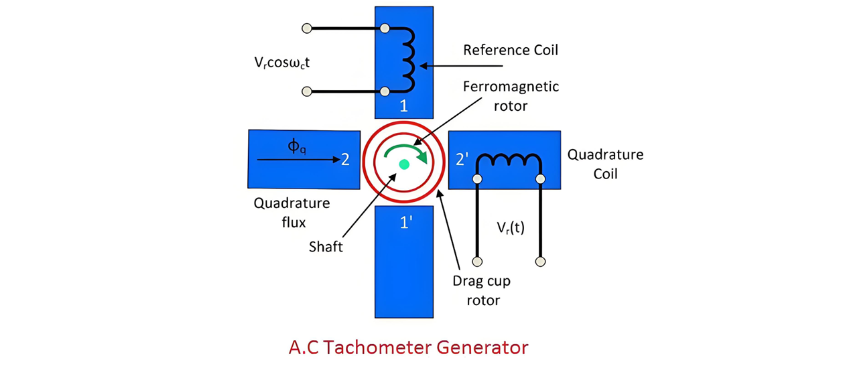
Drag Cup Rotor AC Generator
The drag cup type A.C tachometer is shown in the figure below.
- Structure and Characteristics of AC Tachometer Generator
The stator of the AC tachometer generator is equipped with two distinct windings: the reference winding and the quadrature winding. These windings are positioned at a 90 - degree angle to each other, which is a key aspect of the generator's design for accurate operation. The rotor of the tachometer is crafted from a thin aluminium cup and is situated within the field structure.
Constructed from a highly inductive material, the rotor exhibits low inertia, enabling it to respond quickly to changes in rotational speed. An electrical input is supplied to the reference winding, while the output signal is retrieved from the quadrature winding. As the rotor rotates within the magnetic field, it induces a voltage in the sensing (quadrature) winding. The magnitude of this induced voltage is directly proportional to the rotational speed of the rotor, establishing a reliable mechanism for measuring angular velocity.
Advantages
Ripple - Free Output: The drag cup tachogenerator is notable for producing an output voltage that is free from ripples. This smooth output ensures more accurate and consistent speed measurements, making it well - suited for applications where precise speed monitoring is crucial.
Cost - Effective: Another significant benefit is its relatively low cost. This affordability makes the drag cup tachogenerator an attractive option for a wide range of applications, especially those where cost - effectiveness is a priority without sacrificing basic functionality.
Disadvantage
However, the drag cup tachogenerator has a notable limitation. When the rotor spins at high speeds, a nonlinear relationship emerges between the output voltage and the input speed. This nonlinearity can lead to inaccuracies in speed measurement if not properly accounted for, potentially restricting the generator's use in scenarios that require high - speed and highly precise rotational speed measurements.