Speed Control of DC Motor: Armature Resistance Control and Field Flux Control

Edwiin
05/10/2025
A DC motor is a device that converts mechanical power into direct - current electrical power. One of the most notable characteristics of a DC motor is its ability to have its speed easily adjusted according to specific requirements using straightforward methods. This level of convenient speed control is not as readily achievable with an AC motor.
The concepts of speed regulation and speed control are distinct. In the case of speed regulation, the motor's speed changes spontaneously in response to various operating conditions. Conversely, in a DC motor, speed changes are deliberately initiated either manually by an operator or automatically through control devices. The speed of a DC motor is determined by the following relation:

Equation (1) clearly illustrates that the speed of a DC motor depends on three key factors: the supply voltage V, the armature circuit resistance Ra, and the field flux ϕ, which is generated by the field current.
- When it comes to controlling the speed of a DC motor, the manipulation of voltage, armature resistance, and field flux are crucial considerations. There are three primary techniques for achieving DC motor speed control, as outlined below:
- Variation of Resistance in the Armature Circuit (Armature Resistance or Rheostatic Control)
- Variation in Field Flux (Field Flux Control)
- Variation in Applied Voltage (Armature Voltage Control)
A more in - depth exploration of each of these speed - control methods is provided subsequently.
Armature Resistance Control of DC Motor (Shunt Motor)
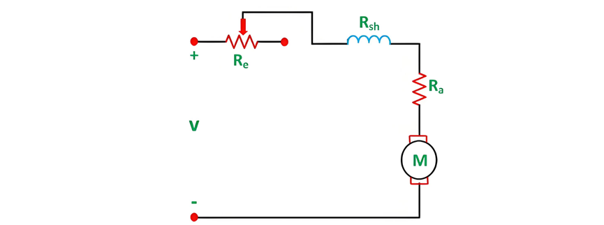
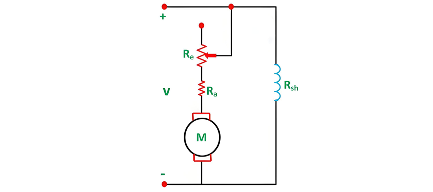
The connection diagram for implementing armature resistance control on a shunt motor is depicted below. In this approach, a variable resistor Re is inserted into the armature circuit. Notably, changes in the value of this variable resistor do not impact the magnetic flux because the field winding is directly connected to the supply mains.
Armature Resistance Control of DC Motor (Shunt Motor)
The connection diagram for implementing armature resistance control on a shunt motor is depicted below. In this approach, a variable resistor Re is inserted into the armature circuit. Notably, changes in the value of this variable resistor do not impact the magnetic flux because the field winding is directly connected to the supply mains.

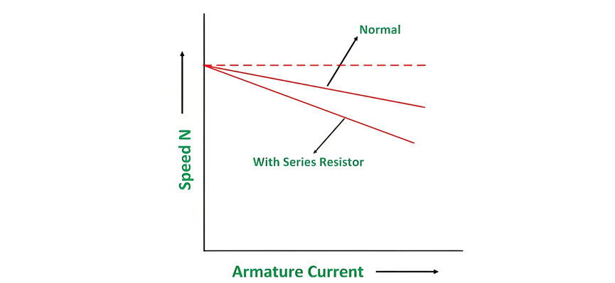
The speed current characteristic of the shunt motor is shown below.
Series Motor
Let's now examine the connection diagram for controlling the speed of a DC series motor using the armature resistance control method.
When the resistance of the armature circuit is adjusted, it simultaneously impacts both the current flowing through the circuit and the magnetic flux within the motor. The voltage drop across the variable resistor effectively diminishes the voltage available to the armature. Consequently, this reduction in applied armature voltage leads to a decrease in the motor's rotational speed.
The speed - current characteristic curve of a series motor, which illustrates the relationship between the motor's speed and the current passing through it, is presented in the figure below.
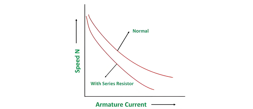
When the value of the variable resistance Re is increased, the motor operates at a lower rotational speed. Given that the variable resistance conducts the entire armature current, it must be engineered to continuously handle the full - rated armature current without overheating or failing.
Disadvantages of the Armature Resistance Control Method
- A significant amount of electrical power is dissipated as heat within the external resistance Re, resulting in inefficiencies and energy waste.
- This method of armature resistance control is limited to reducing the motor's speed below its normal operating speed; it does not allow for an increase in speed beyond the normal level.
- For any specific value of the variable resistance, the degree of speed reduction is not fixed but instead fluctuates depending on the load applied to the motor, making it challenging to achieve precise speed regulation.
- Due to its inherent inefficiencies and limitations, this speed - control approach is typically only suitable for small - sized motors.
Field Flux Control Method of DC Motor
The magnetic flux within a DC motor is generated by the field current. Consequently, speed control using this method is accomplished by adjusting the magnitude of the field current.
Shunt Motor
In a shunt motor, a variable resistor RC is connected in series with the shunt field windings, as illustrated in the figure below. This RC is commonly referred to as a shunt field regulator, playing a crucial role in modifying the field current and, subsequently, the magnetic flux of the motor.
The shunt field current is given by the equation shown below:

When the variable resistor RCis inserted into the field circuit, it restricts the flow of field current. As a result, the magnetic flux generated by the field windings is diminished. This decrease in flux has a direct impact on the motor's speed, causing it to increase. Consequently, the motor operates at a rotational speed that exceeds its normal, unaltered speed.
This unique characteristic makes the field flux control method highly useful for two main purposes. Firstly, it enables the motor to achieve speeds higher than its standard operating speed, providing flexibility in applications that require elevated rotational rates. Secondly, it can be employed to counteract the natural drop in speed that occurs when the motor is under load, effectively maintaining a more consistent speed under varying load conditions.
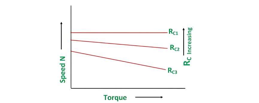
The speed - torque curve for a shunt motor, which graphically illustrates the relationship between the motor's rotational speed and the torque it can produce, is presented below. This curve offers valuable insights into the motor's performance characteristics under different operating scenarios when the field flux control method is applied.
Series Motor
In the case of a series motor, altering the field current can be accomplished through one of two methods: either by utilizing a diverter or by implementing tapped field control.
By Using a Diverter
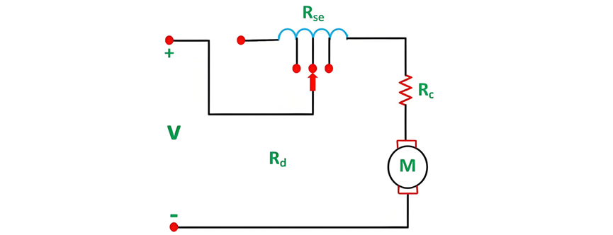
As depicted in the figure below, a variable resistance Rd is connected in parallel with the series field windings. This configuration allows for the manipulation of the current distribution within the circuit, thereby influencing the strength of the magnetic field generated by the series field windings.
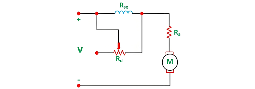
The parallel resistor in this setup is known as a diverter. When the diverter with variable resistance Rd is connected, it diverts a certain fraction of the main current away from the series field windings. Consequently, the primary function of the diverter is to decrease the magnitude of the current passing through the field winding. As the field current diminishes, the magnetic flux generated by the field also reduces. This reduction in flux leads to an increase in the motor's rotational speed.Tapped Field ControlThe second approach for altering the field current in a series motor is through tapped field control. The corresponding connection diagram, which illustrates the specific electrical connections and components involved in this method, is presented below.
In the tapped field control method, the ampere - turns are adjusted by changing the number of active field turns. This particular configuration is highly applicable in electric traction systems. By manipulating the number of field turns, the magnetic field flux generated by the motor's field winding is altered, thereby enabling precise control over the motor's speed.
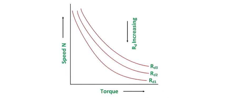
The speed - torque characteristic curve of a series motor, which graphically depicts the relationship between the motor's rotational speed and the torque it can produce under various operating conditions, is illustrated below. This curve provides valuable insights into the motor's performance capabilities when the tapped field control method is employed, helping engineers and technicians understand how the motor responds to changes in load and speed settings.
Advantages of Field Flux Control
The field flux control method offers several notable benefits, as outlined below:
- Ease of Use: This approach is straightforward and user - friendly, facilitating simple implementation and operation.
- Low Power Loss: Given that the shunt field typically has a relatively small current requirement, the power dissipated within the shunt field remains minimal, contributing to improved overall efficiency.
- Speed Increase Mechanism: Due to the saturation of the iron core in the magnetic circuit, the magnetic flux generally cannot be increased beyond its normal value. As a result, field flux control primarily focuses on weakening the field, which effectively leads to an increase in the motor's rotational speed.
- Controlled Application Range: However, it's important to note that this method is applicable only within a restricted range. Excessive weakening of the field can lead to instability in the motor's operation, limiting its use to specific scenarios where precise control and stability are crucial.
Topics