Analysis and Treatment of Fault Causes of 35 kV Outdoor Vacuum Circuit Breaker

Fault Phenomenon
On June 23, 2020, a fault occurred in the 35 kV feeder bay that was on hot standby at a 220 kV substation. This triggered the operation of the first - stage, first - time - limit voltage - restrained overcurrent protection of the low - voltage backup protection of the No. 2 main transformer and the second - stage overcurrent protection of the 350 bus tie protection. Consequently, the 352 circuit breaker on the low - voltage side corresponding to the No. 2 main transformer and the 350 bus tie circuit breaker tripped, resulting in the loss of voltage on the 35 kV Section I bus of the substation.
Prior to the accident, the 35 kV system of the substation adopted a single - bus sectionalized connection mode. A dedicated bus tie circuit breaker was installed between the two bus sections. The 35 kV Section I bus where the faulty bay was located had a total of three outgoing lines and two capacitor banks. The faulty bay was on hot standby, and its protection function was not activated. The remaining bays were in operation, and the bus tie circuit breaker was in the closed position.
Cause Analysis
By examining the message reports and oscillograms from the protection devices of the 350 bus tie bay and the No. 2 main transformer bay at the substation, it was found that at the onset of the fault, it initially manifested as a phase - to - phase fault between phases B and C, which subsequently escalated into a three - phase short - circuit fault. Specifically, the fault waveform diagram (screenshot) of the low - voltage side of the No. 2 main transformer is illustrated in Figure 1.
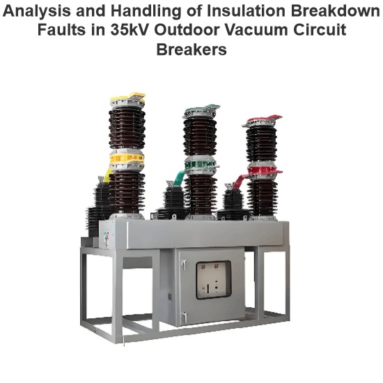
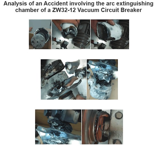
Upon inspection of the faulty circuit breaker, it was discovered that after the occurrence of the fault, the bushing of phase A of the vacuum circuit breaker had fractured, the post porcelain insulators of phases B and C were severely burned and damaged, and the lead wires of the circuit breaker had broken strands to varying degrees. There were no signs of electrical discharge observed on the busbar connection busbars, the wall - bushing insulators, or the disconnectors on the busbar side of the circuit breaker. The damage status of the primary equipment was inspected on - site, as depicted in Figure 2.
The following is an in - depth analysis of the causes of the circuit breaker failure.

Reasons Related to Circuit Breaker Quality
The circuit breaker in question is of the LW8 - 35A (T) type. It was installed and commissioned on site in December 2007 and put into operation in March 2008. Currently, there are 11 vacuum circuit breakers of the same model at the substation, all of which are arranged outdoors. Upon on-site inspection of the mechanism of this model of circuit breaker, discharge marks of varying degrees were found on the post porcelain insulators. By checking the fault recorder in the substation, it was noted that the 35 kV bus voltage frequently exceeded the limit and initiated trips before the fault occurred. This frequent over-limit variation strongly confirms the presence of discharge marks on the post porcelain insulators of this type of circuit breaker.
A withstand voltage test was conducted on the post porcelain insulators of the remaining 10 circuit breakers of the same model in the substation. Nine of them passed the test, and only one did not meet the requirements of the test regulations. When the faulty bay was tested again, it passed the withstand voltage test. Therefore, the possibility of the circuit breaker's quality being the cause of the fault can be basically ruled out.
Reasons Related to Circuit Breaker Operation and Maintenance
This 220 kV substation is located at the junction of urban and rural areas, adjacent to a quarry, and there is a relatively serious problem of dust pollution in the vicinity. On-site inspection revealed that there was a significant amount of dust accumulation on the surface of the post porcelain insulators of the faulty circuit breaker. In a polluted environment, the insulation performance of post porcelain insulators will decrease.
Due to the importance of the users connected to the outgoing lines of the 35 kV system in this substation, it was difficult to carry out power outages. As a result, the circuit breaker could not be inspected and maintained in a timely manner. The flashover voltage of the post porcelain insulators of the circuit breaker decreases as the degree of pollution increases. The cumulative effect over time caused the flashover voltage to drop below the operating voltage, leading to electrical discharge. On the day of the fault, there was continuous rainy weather in the local area, and the increased humidity in the atmosphere further exacerbated this process. Therefore, it can be determined that this was an accident caused by flashover due to contamination.

Fault Handling
The faulty circuit breaker was replaced. After on-site commissioning, the test data of the new circuit breaker met the requirements specified in the ex-factory technical documents. Currently, the circuit breaker is operating stably.
Power outages were carried out to inspect the circuit breakers of the same model in the substation. The contaminants were cleaned and wiped off, and insulation spraying was carried out again. A comprehensive inspection, maintenance, and characteristic test were conducted on each circuit breaker, and other problems found were rectified in a timely manner. At present, the other 10 outdoor circuit breakers of the same model in the substation are operating stably.
In the next step, a comprehensive inspection and technical renovation will be carried out on outdoor circuit breakers in such areas. They will be centrally replaced with Gas Insulated Switchgear (GIS) equipment to fundamentally prevent accidents caused by flashover due to contamination in areas with severe dust pollution.
Preventive Measures
Design units should improve their design level, optimize the design structure, and enhance the insulation performance of circuit breakers in areas with severe air pollution (such as building shelters or using GIS equipment).
Equipment manufacturing units should strictly control the quality management of equipment and earnestly implement the technological requirements of each link in the equipment manufacturing, assembly, and commissioning processes.
Operation and maintenance units should do a good job in the daily maintenance and inspection of equipment. They should attach great importance to protection signals in the substation, especially signals such as the frequent activation of the fault recorder. They should carefully investigate and analyze problems, identify the actual operating status of the equipment behind the signals, and promptly conduct evaluation and analysis of the equipment.
Equipment management units should do a good job in the acceptance of new equipment entering the grid, strengthen the daily management of equipment, and improve the reliability of power supply.
Hey there! I'm an electrical engineer specializing in Failure and Maintenance. I've dedicated my career to ensuring the seamless operation of electrical systems. I excel at diagnosing complex electrical failures, from malfunctioning industrial motors to glitchy power distribution networks. Using state - of - the - art diagnostic tools and my in - depth knowledge, I pinpoint issues quickly. On this platform, I'm eager to share my insights, exchange ideas, and collaborate with fellow experts. Let's work together to enhance the reliability of electrical setups.