Performance characteristics and structural design of outdoor pole-mounted vacuum circuit breakers

From 2009 to 2010, the State Grid was in the pilot phase of the smart grid planning, focusing on developing the strong smart grid development plan, conducting research and development of key technologies, manufacturing equipment, and carrying out pilot projects in various sectors. The period from 2011 to 2015 marked the full - scale construction phase, during which an operational control and interactive service system for the smart grid was initially formed, and significant breakthroughs were achieved in key technologies and equipment, leading to their extensive application.
From 2016 to 2020, it entered the leading and upgrading stage, with a unified and strong smart grid fully established, and the technologies and equipment reaching international advanced levels. By then, the grid's ability to optimize resource allocation will be greatly improved.To respond to the development goals of the national smart grid, outdoor pole - mounted vacuum circuit breakers installed on major power grids are required to achieve microcomputer - based intelligent protection with high sensitivity, which means a low minimum primary operating current value.
Therefore, in addition to each of the three phases being equipped with a separate current transformer for differential protection, outdoor pole - mounted vacuum circuit breakers also need to be equipped with residual current transformers for microcomputer protection to provide precise leakage protection for the microcomputer. Traditional residual current transformers are large in size, heavy in weight, and low in accuracy.
Affected by factors such as limited installation space and long secondary lead circuits, they can hardly meet the application requirements of microcomputer protection for outdoor pole - mounted vacuum circuit breakers. Currently, all outdoor circuit breakers that can meet the requirements of the national smart grid are produced by foreign - funded enterprises, resulting in high costs. To adapt to the development requirements of the national smart grid, it is necessary to develop outdoor circuit breakers that meet the needs of the national smart grid.
At present, the primary technical challenge we need to address is to develop residual current transformers for microcomputer protection that can be used in conjunction with these circuit breakers, meeting the requirements of installation in small spaces, high - sensitivity leakage microcomputer protection, and accurate operation, and first achieving the localization of residual current transformers for microcomputer protection.
Applications and Performance Requirements of Residual Current Transformers for Microcomputer Protection
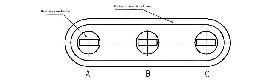
The residual current transformer (zero - sequence current transformer) is a specialized current transformer designed to transform residual current (zero - sequence current). It is used for single - phase grounding protection in neutral - insulated systems. The three - phase conductors pass through the core window of the transformer simultaneously, serving as the primary winding of the transformer.
When the system operates normally, the phasor sum of the three - phase currents is zero, and there is no output from the secondary side of the residual current transformer. When a single - phase grounding fault occurs in a certain line, the primary current of the residual current transformer reaches the minimum operating current of the relay or microcomputer protection, triggering the protection device to act.
Otherwise, it remains inactive.In traditional residual current transformers, the secondary side is directly connected to a relay. Since the number of turns in the primary winding of the transformer is usually 1, the number of turns in the secondary winding is very small. The minimum primary operating current of traditional residual current transformers is mostly between 2.4A and 10A, and the rated primary current of traditional residual current transformers is generally selected in the range of 15A to 300A. To meet the accuracy requirements, the core cross - sectional area of the transformer is designed to be relatively large, resulting in a large size, heavy weight, low accuracy, and small secondary load.
When the fault current is less than 2.4A, the current output by the traditional transformer is insufficient to activate the relay, creating a "dead zone." Therefore, to enable the transformer to provide accurate protection for the microcomputer within a wide range of operating currents without a dead zone, it is necessary to design a special residual current transformer that can be used in conjunction with microcomputer protection.
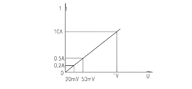
Restricted by the installation space of the circuit breaker, the special residual current transformer used with microcomputer protection not only needs to be small in size and light in weight but also requires high - precision secondary output and a large secondary load. Generally, the primary operating current of the transformer is required to be between 0.2A and 10A. If the transformer can ensure good linearity and sensitivity under the condition of a large secondary load output, it can meet the requirements of microcomputer protection and avoid the occurrence of a "dead zone."
Structural Design of Residual Current Transformers for Microcomputer Protection
Selection of Rated Load Parameters of the Transformer
Outdoor pole - mounted vacuum circuit breakers are generally installed outdoors and are far from the supporting automation devices. However, the load required by the microcomputer protection itself is very low. When designing the residual current transformer, the rated load mainly considers the load of the secondary lead circuit of the transformer. Since the microcomputer protection device is usually far from the pole - mounted circuit breaker installed outdoors, the rated load of the transformer is generally selected to be relatively large, with the maximum reaching about 200Ω (this load can be determined according to the actual situation of the user).
Selection of the Number of Turns of the Primary and Secondary Windings, Core Shape, and Material
Residual current transformers for microcomputer protection require extremely high sensitivity and must respond promptly and accurately. Sensitivity refers to the ability of the secondary winding of the transformer to respond to leakage current, which can be described as follows: under a certain amount of leakage current, the higher the induced electromotive force of different transformers, the higher their sensitivity.
Sensitivity is related to the number of turns of the primary and secondary windings of the transformer. The more turns in the secondary winding, the higher the sensitivity. The residual current transformer is directly installed on the three - phase primary conductors, and the primary wire is the protected line, with the number of primary turns being 1. Increasing the number of primary turns is not practical.
The induced electromotive force of the secondary winding, U2=4.44f⋅N2⋅μ⋅I1⋅S, where:
-
I1represents the rated primary current.
-
S is the cross-sectional area of the iron core.
-
muis the magnetic permeability.
-
f is the frequency.
-
N2 is the number of turns of the secondary winding.
As can be seen from the formula, due to the limitations of the installation position of the transformer, the external dimensions of the transformer cannot be very large. Thus, the cross-sectional area of the iron core of the transformer is relatively small. To enhance the sensitivity of the transformer, it is necessary to either increase the number of turns of the secondary winding or improve the magnetic permeability of the iron core of the transformer.
The rated primary current of outdoor circuit breakers is basically 630A or less. Given the small cross-sectional area of the iron core of the transformer, in order to ensure high sensitivity, through experiments, the number of turns of the secondary winding is generally initially set between 1500 and 2000 turns. The specific number of turns can be determined according to the secondary load and the secondary output voltage of the transformer required by the microcomputer.
Once the cross-sectional area of the iron core, the number of turns, and the secondary load are determined, the parameter that affects the secondary induced electromotive force (i.e., sensitivity) of the
transformer is only related to the magnetic permeability of the iron core. Therefore, determining the material of the iron core used in the transformer is of crucial importance. The linearity and residual characteristics of the transformer mentioned later are also closely related to the material of the iron core.

transformer is only related to the magnetic permeability of the iron core. Therefore, determining the material of the iron core used in the transformer is of crucial importance. The linearity and residual characteristics of the transformer mentioned later are also closely related to the material of the iron core.
When designing this residual current transformer, the following points should be noted:
Focused on the design of electrical equipment, proficient in electrical principles and relevant specifications, and skilled in using design software. From intelligent substations to various types of electrical equipment, I am adept at optimizing design solutions, integrating new technologies. With practical experience and collaborative management capabilities, I deliver outstanding electrical design achievements.