What is Phasor Diagram for Synchronous Motor?

What is Phasor Diagram for Synchronous Motor?
Phasor Diagram Definition
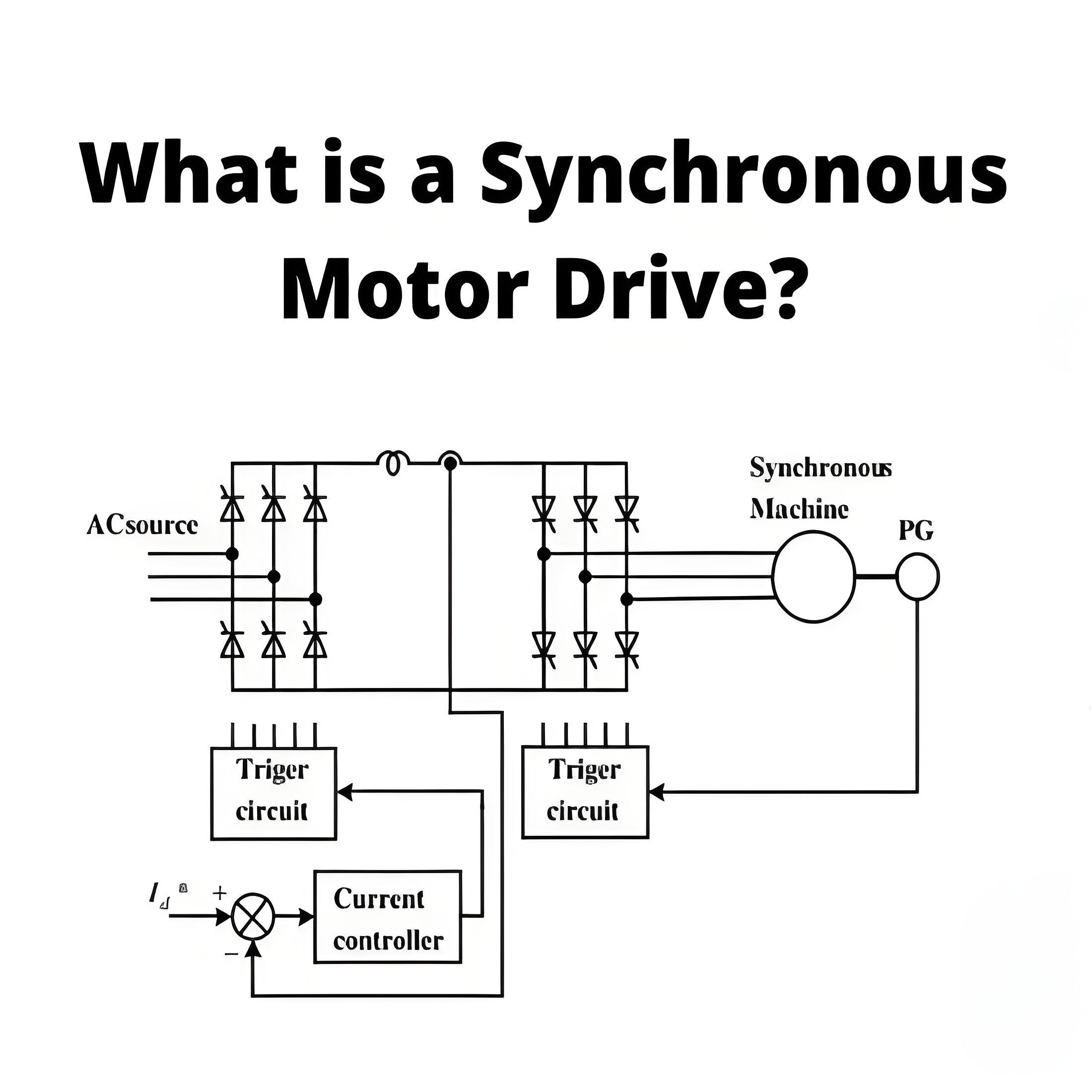
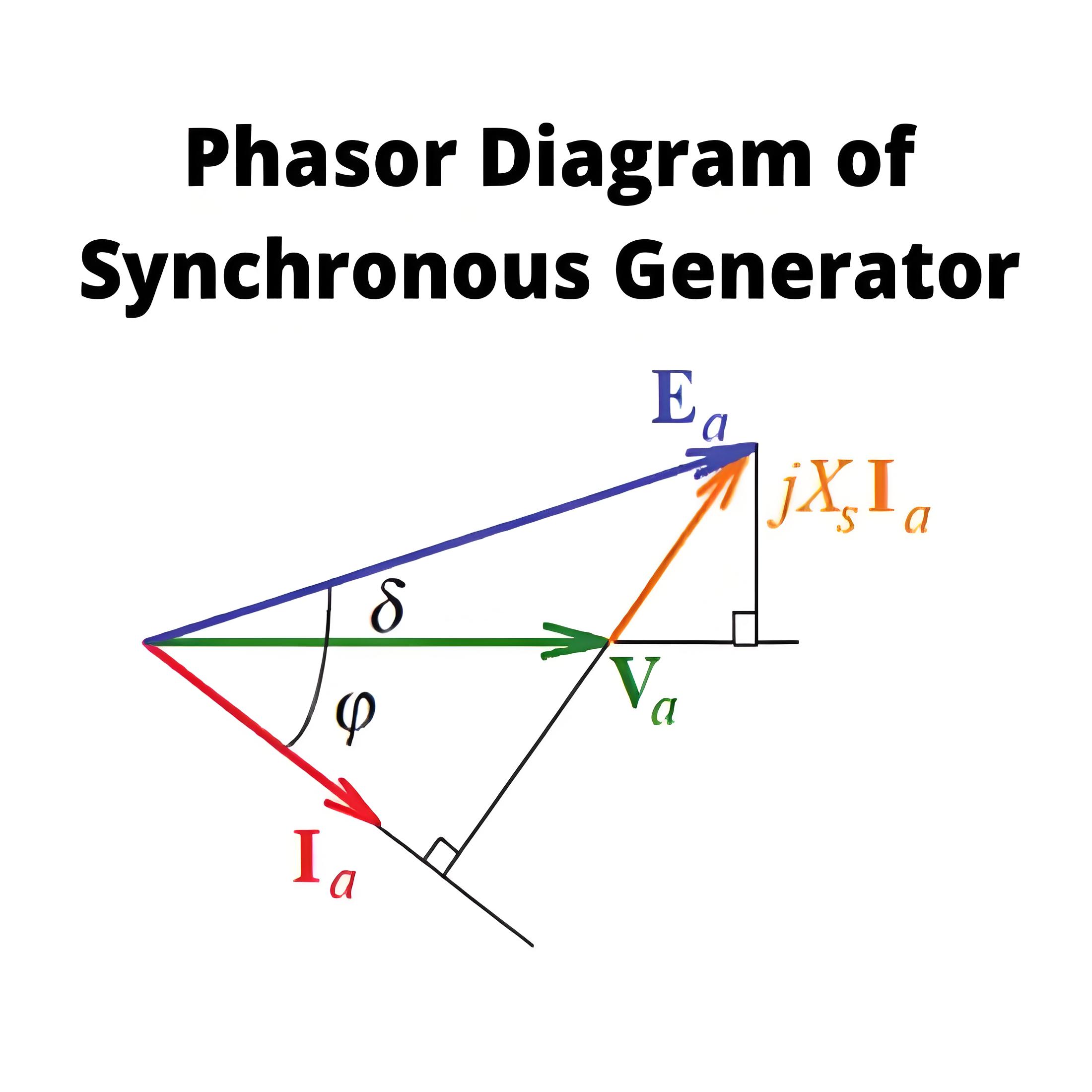
A phasor diagram for a synchronous motor shows the relationships between various electrical quantities like voltage and current.

Ef to represent the excitation voltage
Vt to represent the terminal voltage
Ia to represent the armature current
Θ to represent the angle between terminal voltage and armature current
ᴪ to represent the angle between the excitation voltage and armature current
δ to represent the angle between the excitation voltage and terminal voltage
ra to represent the armature per phase resistance.
Reference Phasor
Vt is the reference phasor, with armature current and excitation voltage being plotted in relation to it.
Opposite Phases
The armature current is in phase opposition to the excitation emf in a synchronous motor.
Power Factor Operations
Different power factor operations (lagging, unity, leading) affect the expressions for the excitation emf, using components of terminal voltage and armature current.

Motoring operation at lagging power factor.
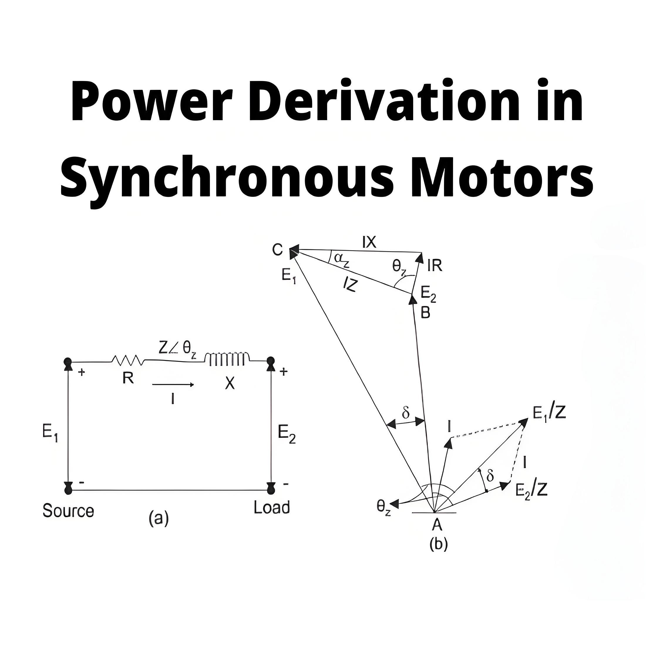
Motoring operation at lagging power factor: In order to derive the expression for the excitation emf for the lagging operation we first take the component of the terminal voltage in the direction of armature current Ia. Component in the direction of armature current is VtcosΘ.
As the direction of armature is opposite to that of the terminal voltage therefore voltage drop will be –Iara hence the total voltage drop is (VtcosΘ – Iara) along the armature current. Similarly we can calculate the voltage drop along the direction perpendicular to armature current. The total voltage drop comes out to be (Vtsinθ – IaXs). From the triangle BOD in the first phasor diagram we can write the expression for excitation emf as
Motoring operation at unity power factor.
Motoring operation at unity power factor: In order to derive the expression for the excitation emf for the unity power factor operation we again first take the component of the terminal voltage in the direction of armature current Ia. But here the value of theta is zero and hence we have ᴪ = δ. From the triangle BOD in the second phasor diagram we can directly write the expression for excitation emf as

Motoring operation at leading power factor.
Motoring operation at leading power factor: In order to derive the expression for the excitation emf for the leading power factor operation we again first take the component of the terminal voltage in the direction of armature current Ia. Component in the direction of armature current is VtcosΘ. As the direction of armature is opposite to that of the terminal voltage therefore voltage drop will be (–Iara) hence the total voltage drop is (VtcosΘ – Iara) along the armature current. Similarly we can calculate the voltage drop along the direction perpendicular to armature current. The total voltage drop comes out to be (Vtsinθ + IaXs). From the triangle BOD in the first phasor diagram we can write the expression for excitation emf as

Advantages of Phasor Diagrams
Phasors are highly useful for gaining physical insight into the operation of the synchronous motors.
We can derive mathematical expressions for various quantities easily with the help of phasor diagrams.
The Electricity Encyclopedia is dedicated to accelerating the dissemination and application of electricity knowledge and adding impetus to the development and innovation of the electricity industry.